This instructions are for printer #0095 and above or if you upgrade to a laser cutted extruder.
Last Update: 19.03.2015
PDF Version
Please contact us if you have any hint to make this document better!
Table of Contents
- Step 00 – General Instructions
- Step 01 – Assembly Holder Z-Motor
- Step 02 – Assembly Spool Holder
- Step 03 – Assembly LCD housing
- Step 04 – Extruder Carriage
- Step 05 – X-Motor Mount
- Step 06 – X-Idler Assembly
- Step 07 – Y-Table Assembly
- Step 08 – Mainframe Assembly
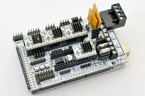
- Step 09 – RAMPS
- Step 10 – Power Supply
- Step 11 – Preparation X-Axis
- Step 12 – Preparation Y-Axis
- Step 13 – Y-table and heated bed platform
- Step 14 – Y-axis
- Step 15 – Z-Axis
- Step 16 – Extruder
- Step 17 – Installation LCD Panel
- Step 18 – Final Assembly
- [wiring overview(#wiring-overview)
- Step 19 – Check Motors And Endstops
- Step 20 – Adjust Heated Bed
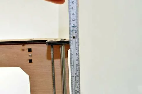
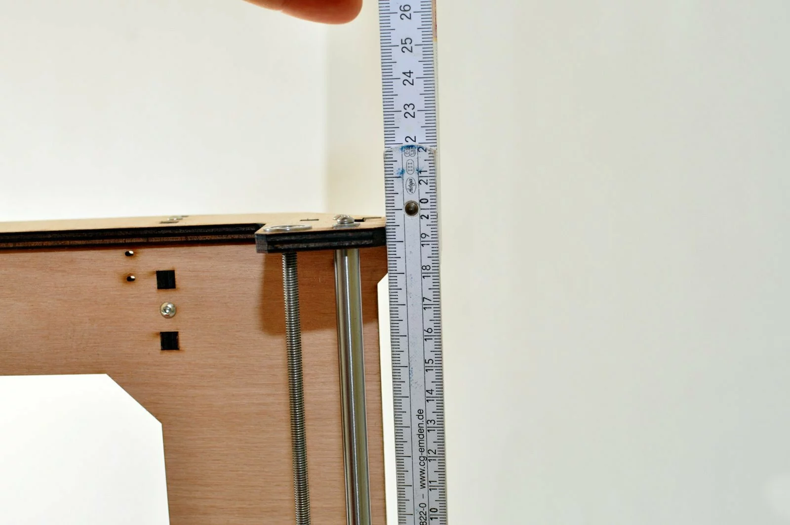
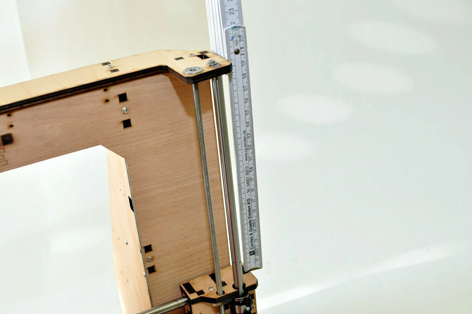
- Step 21 – Z Height
- Step 22 – First Print
Step 00
Before you start – a few annotations:
This V3 document is marked as work in progress. We have already had the version V1 and V2 of the documentation and noticed during our workshops that people use to pay more attention to images than to text. This is why version 2 mainly consists of images rather than text. With this 3rd iteration of the build instructions we have also updated some minor changes. Especiially the routing of the cables and the change of x- axis and y – axis is something that differs to our older instructions. The most significant change is our new compact lasercut extruder – it has less parts – is easier to assemble and offers improved print quality with its full metal hot end equipped with a smaller nozzle. Overall we have cleaned up the latest iterartion of the printer, and are preparing to introduce a dual extruder and a Z-axis extension to 300mm which will be available soon. If you miss an explanation or you think some more words are required please make a note. We really appreciate the feedback from our users.
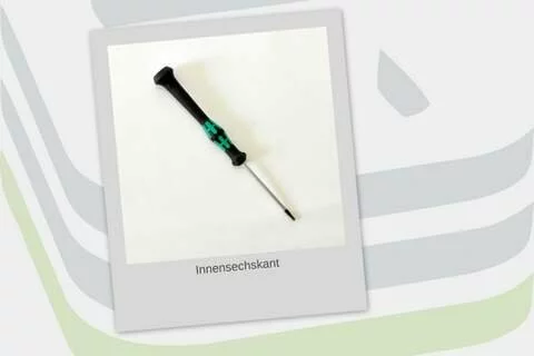
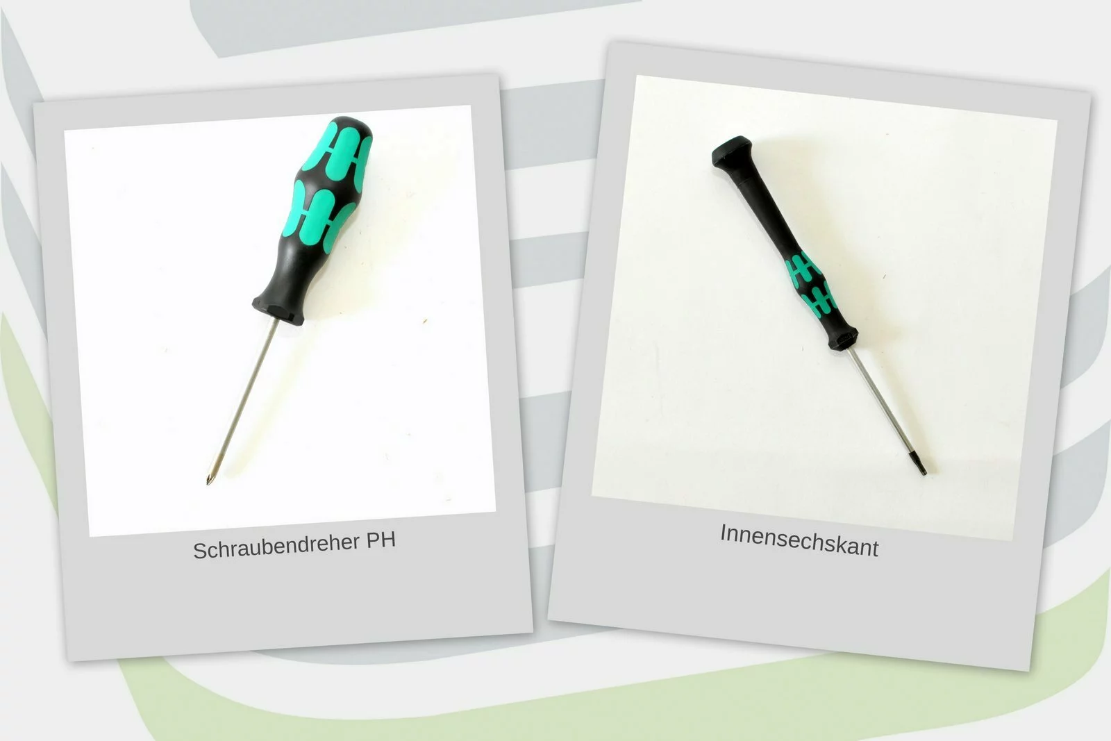
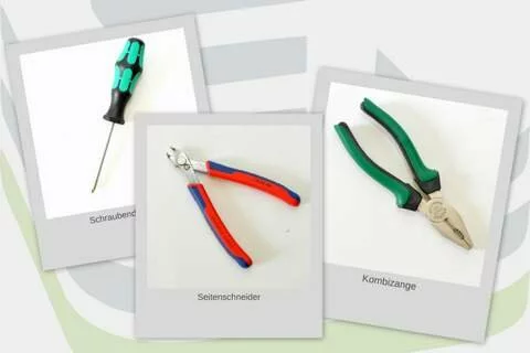
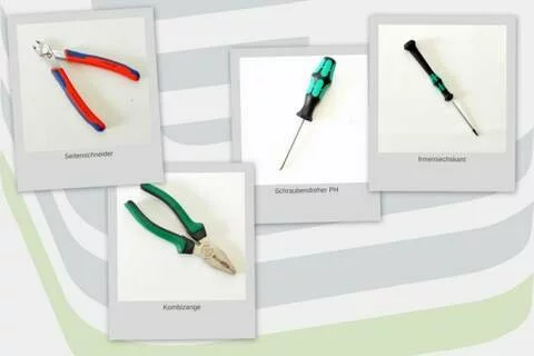
Needed tools
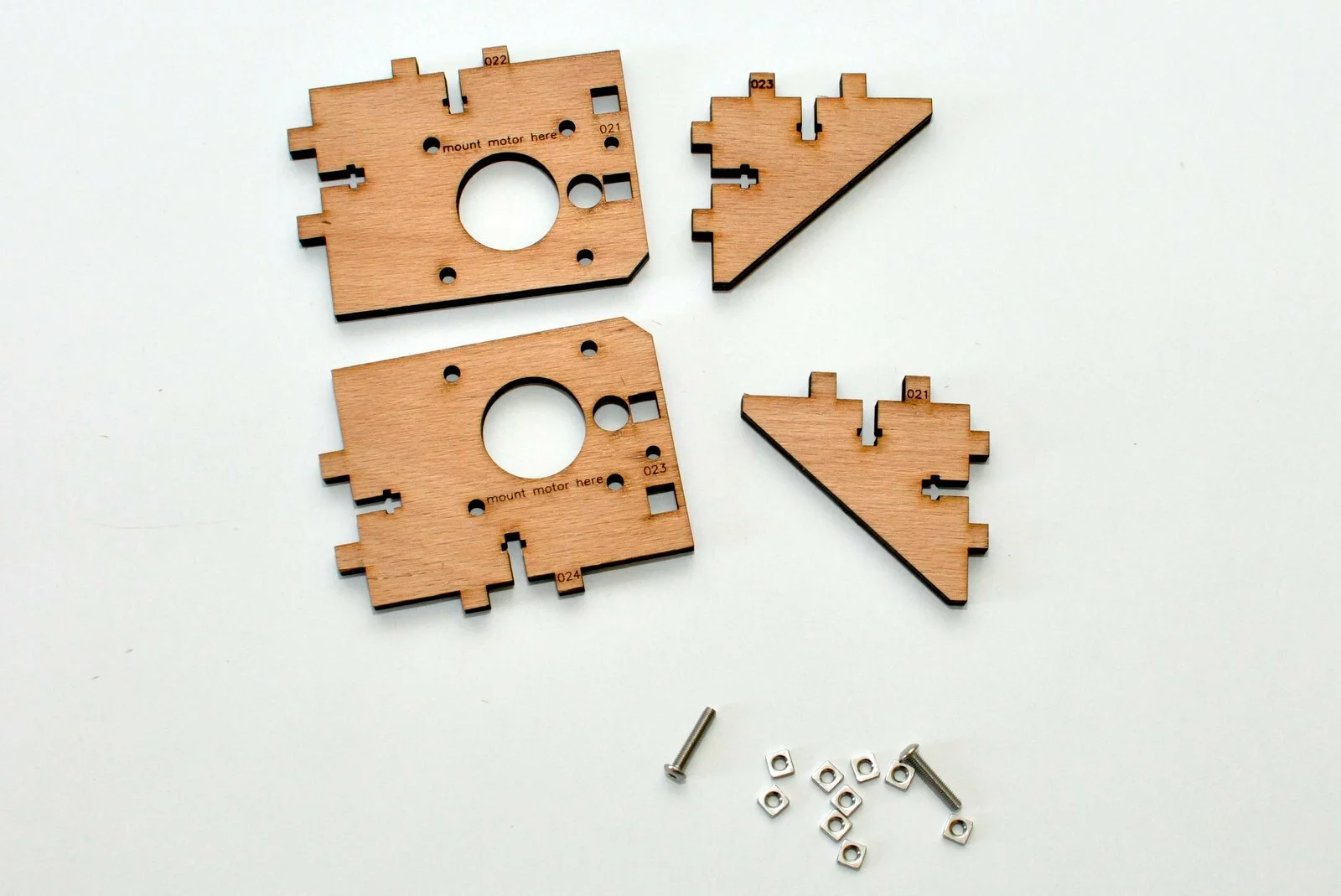
Assembly of laser cut parts
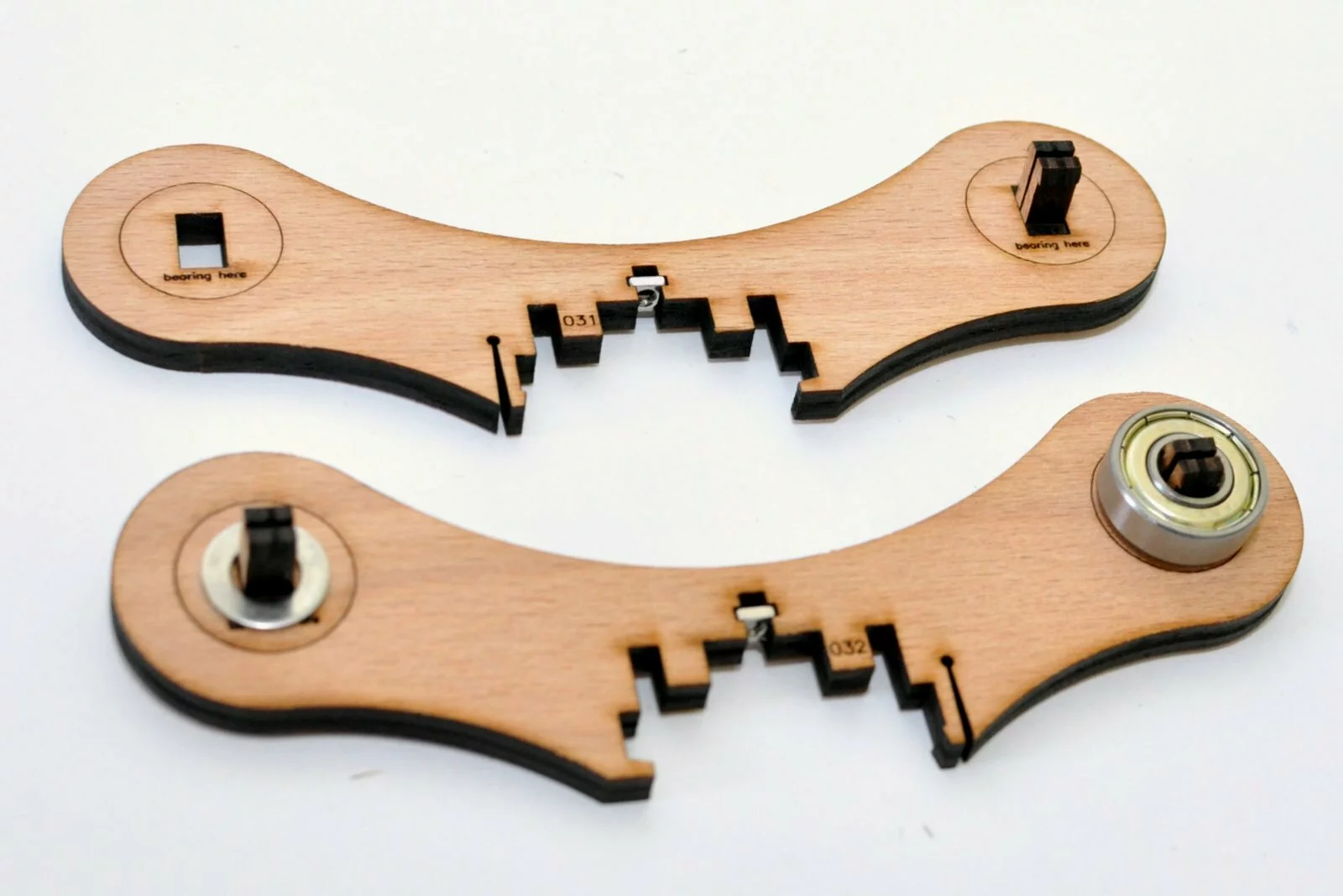
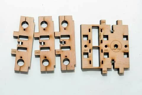
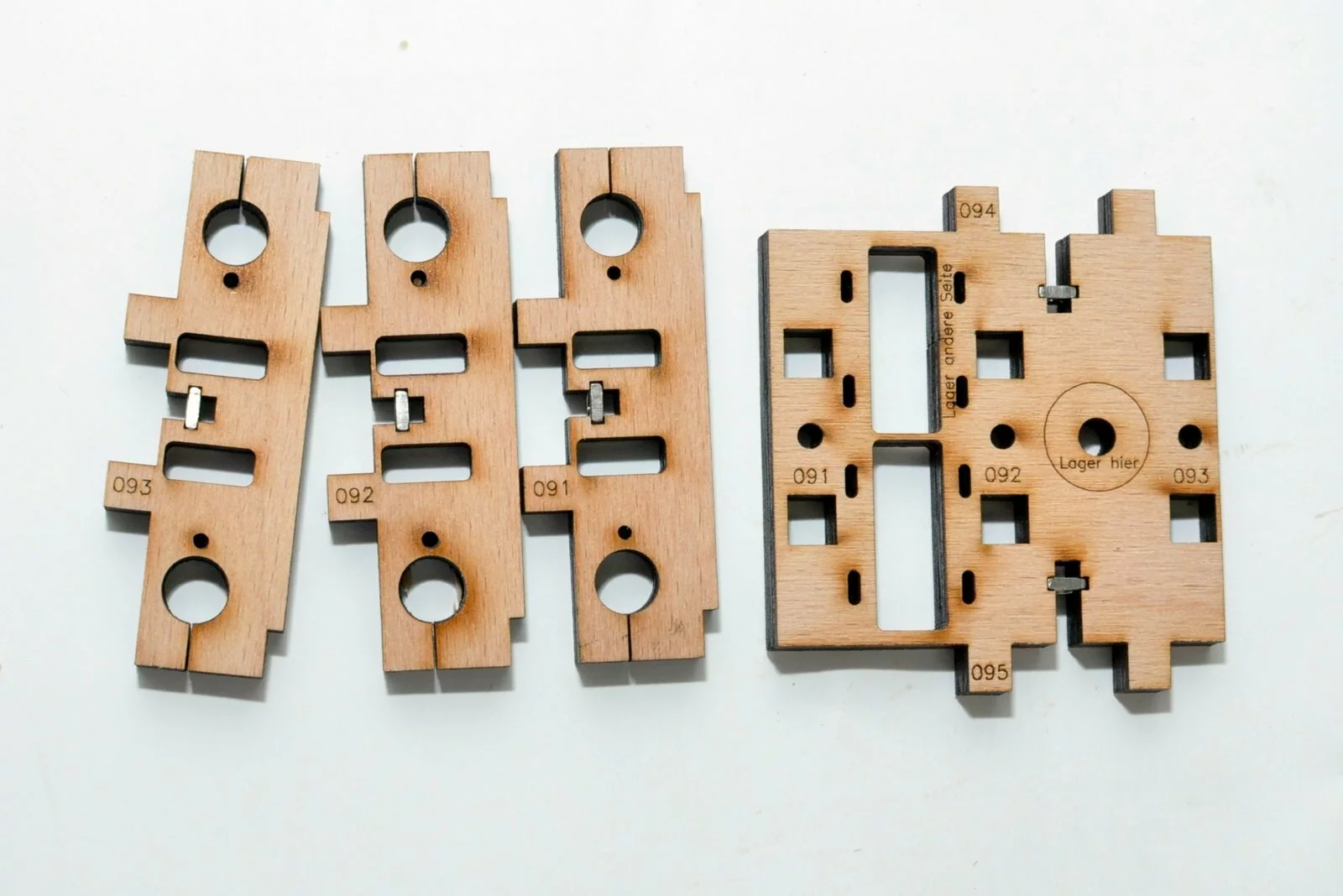
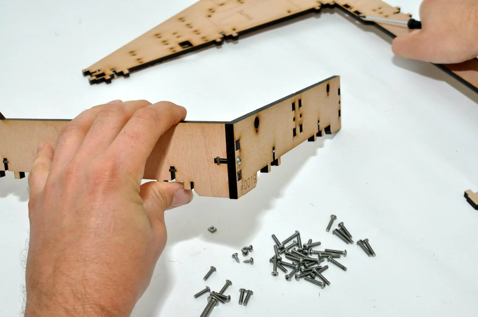
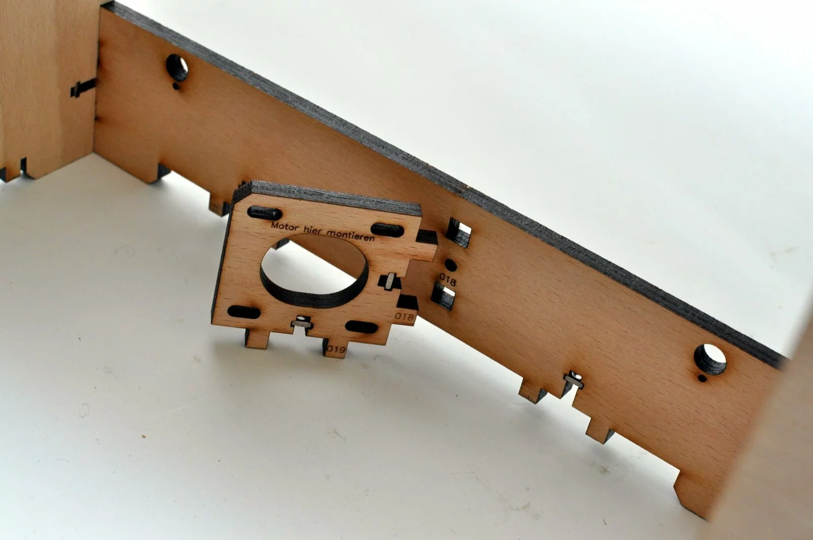
The laser parts contain numbers on the connections. The numberation consist of three numbers. The first two numbers indicate the assembly number ( In the first step we start with the z-motor mounts which have number 2……sorry for that) the third number indicates the connection numberation within the assembly.
It is necessary to mount the parts in the given connection numeration. Otherwise this instruction may eventually not work and you will need to dissassemble parts.
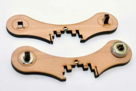
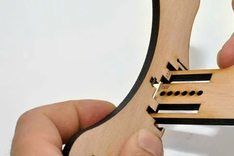
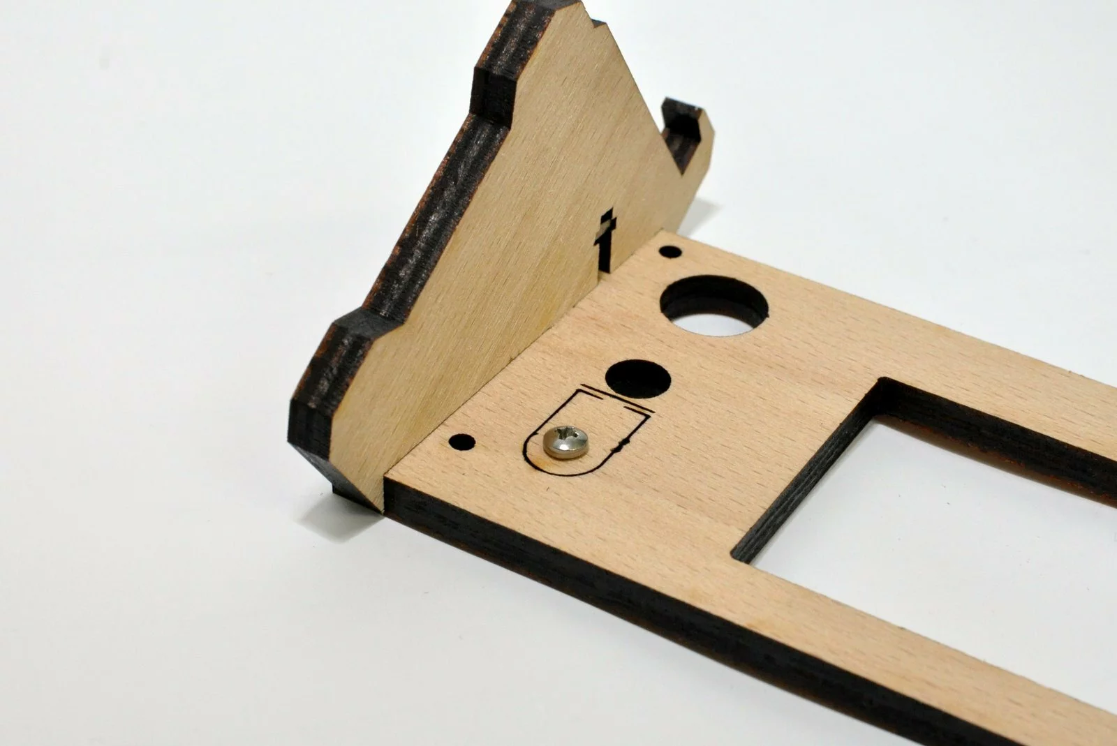
Furthermore there’s two types of connections indicated by different position of the numbers on the parts.
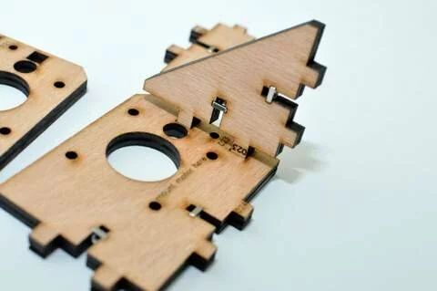
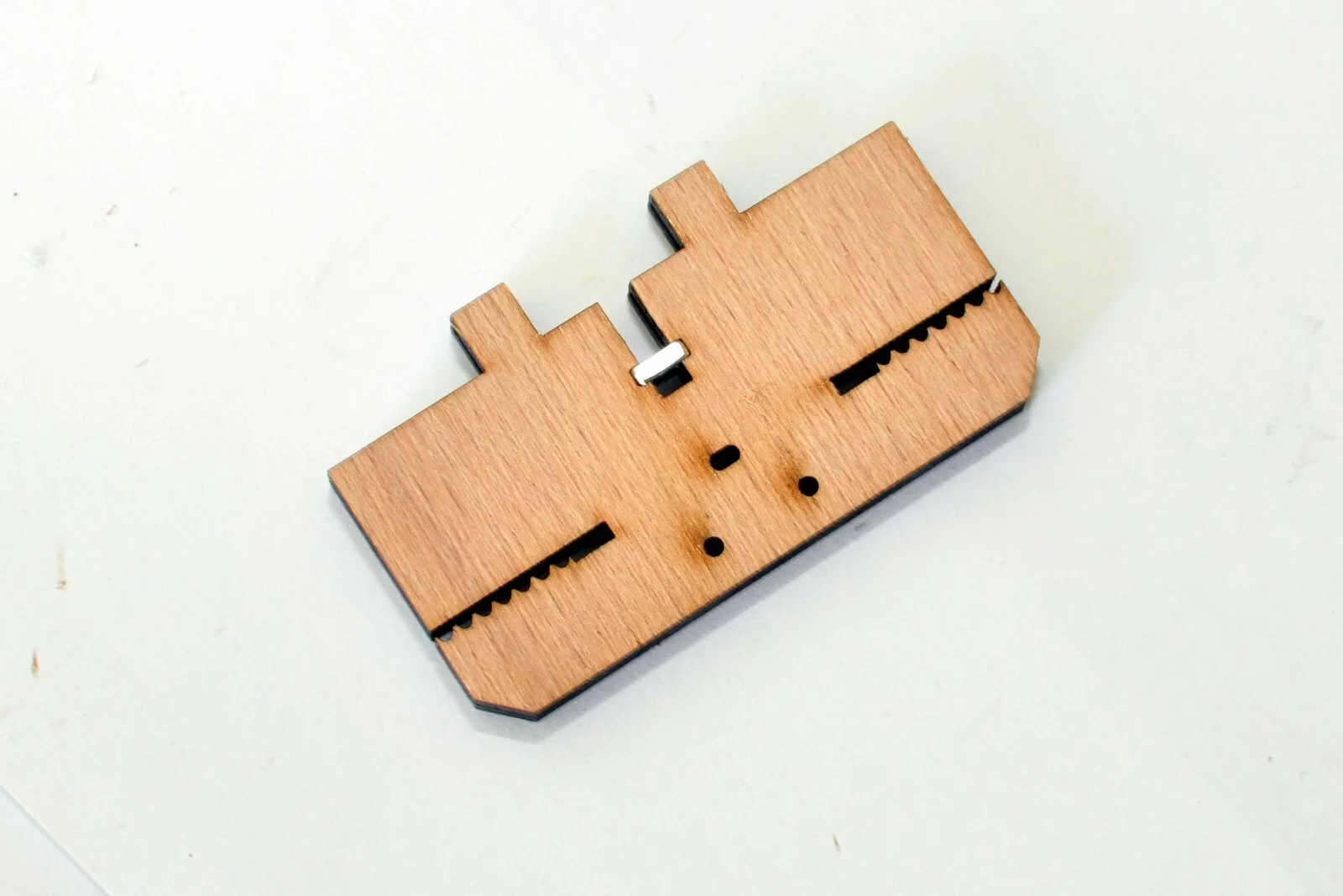
1st type: numbers are placed on the part so that they will get hidden if the parts are assembled:
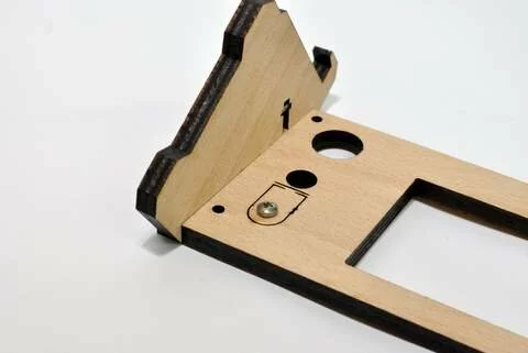
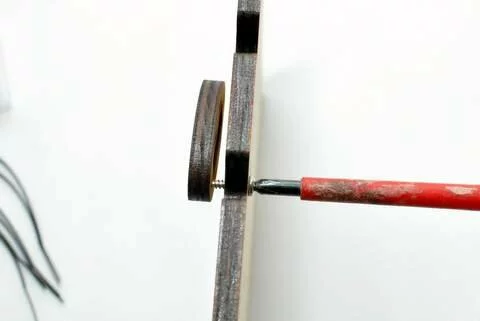
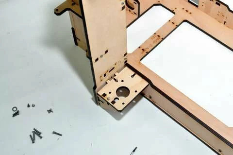
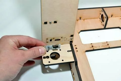
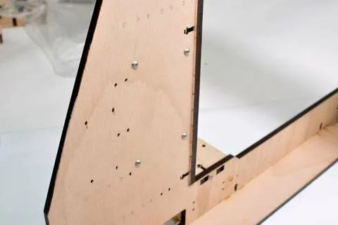
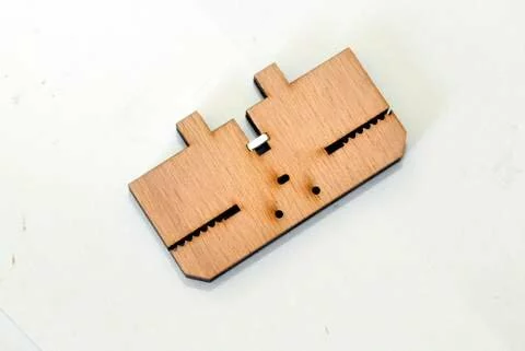
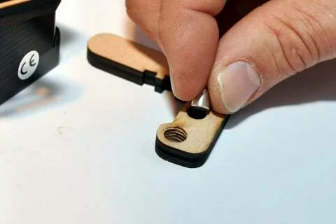
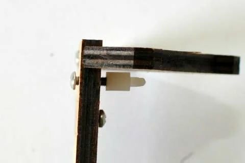
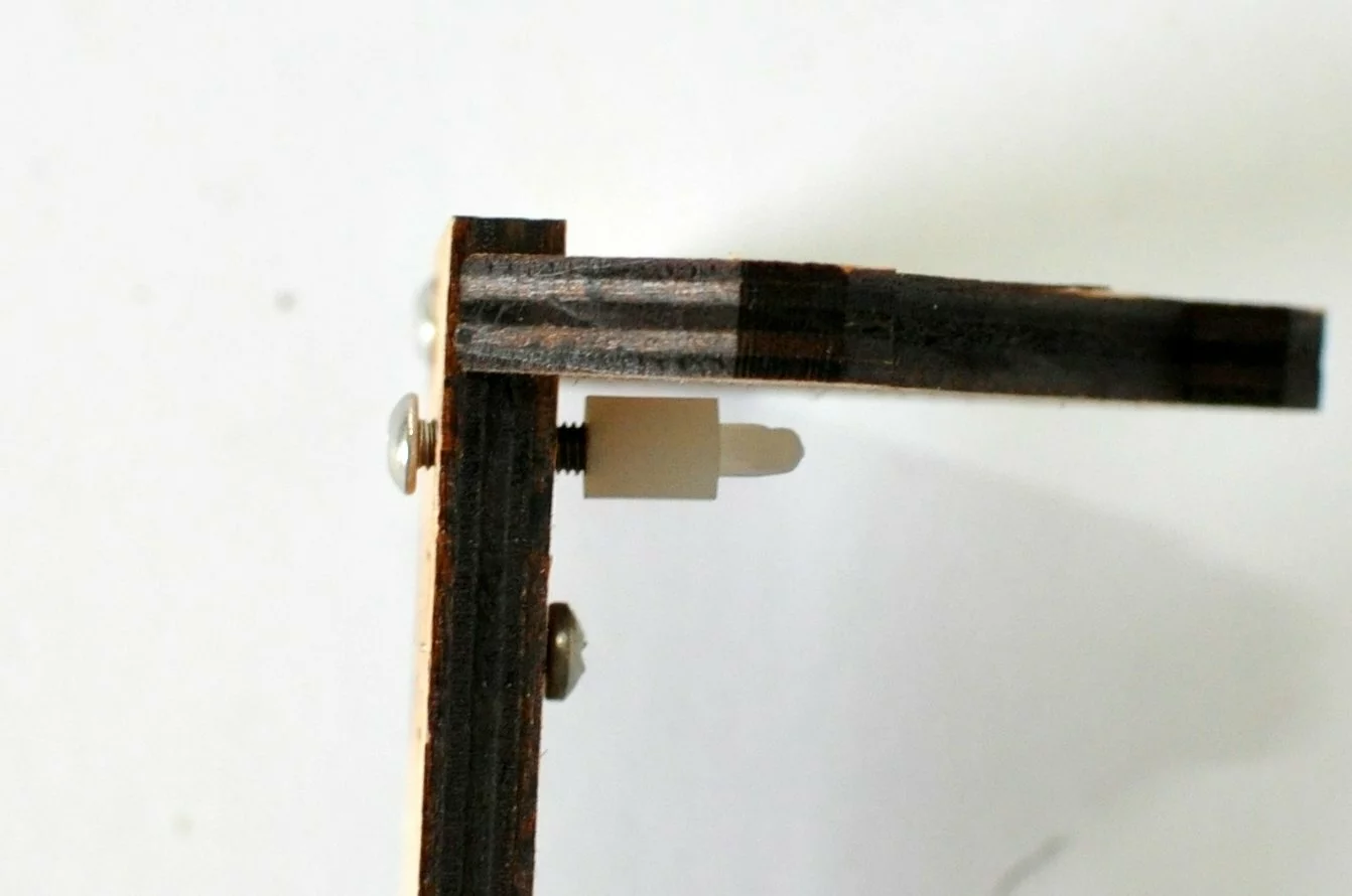
2nd type: numbers are placed so that they won’t get hidden by the part – this means that the part needs to be mounted from the backside (the side without numbers is called backside) see image below.
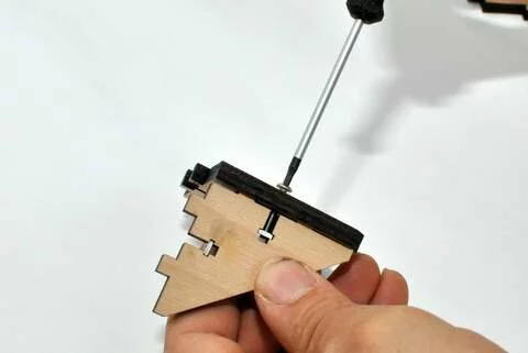
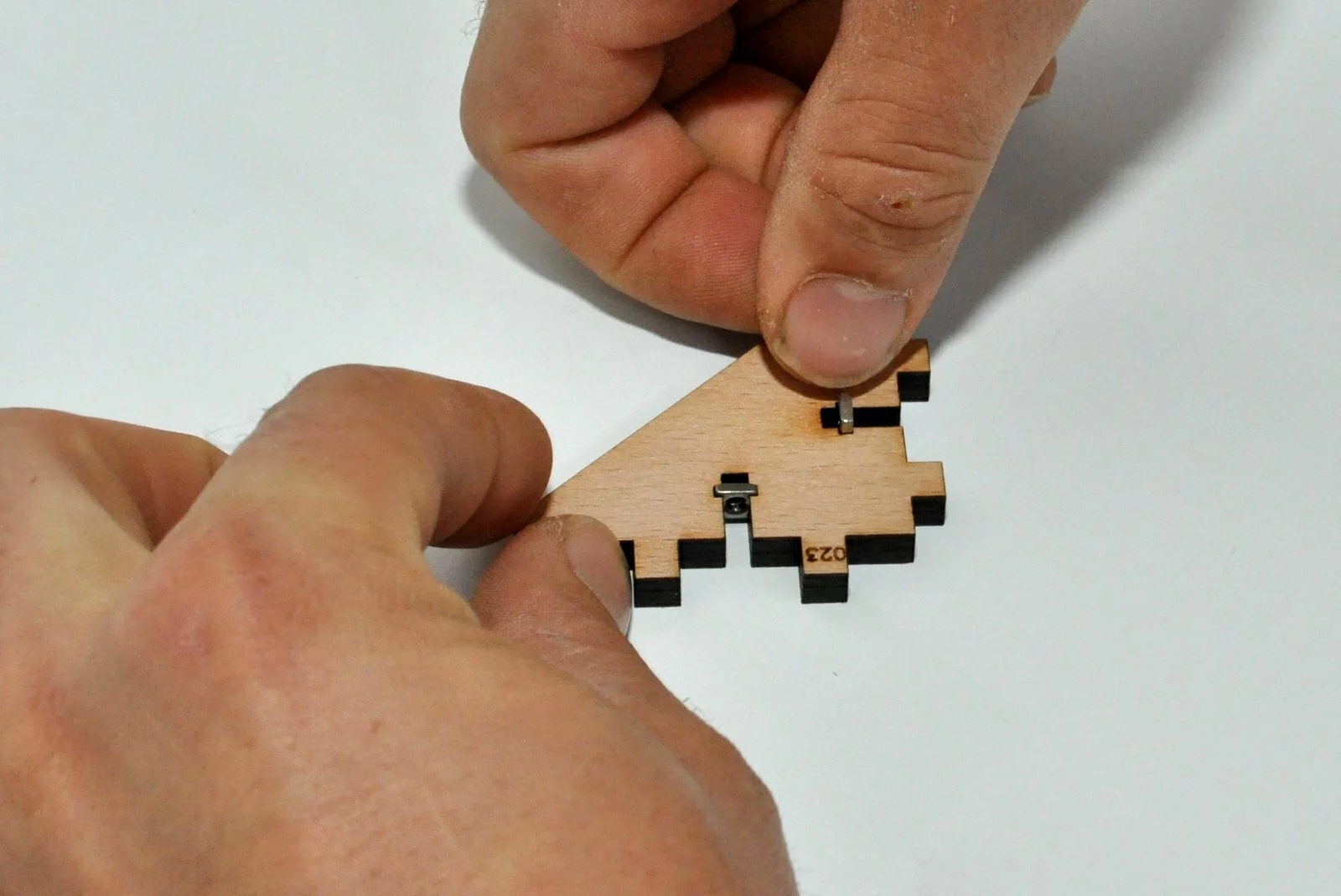
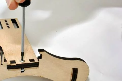
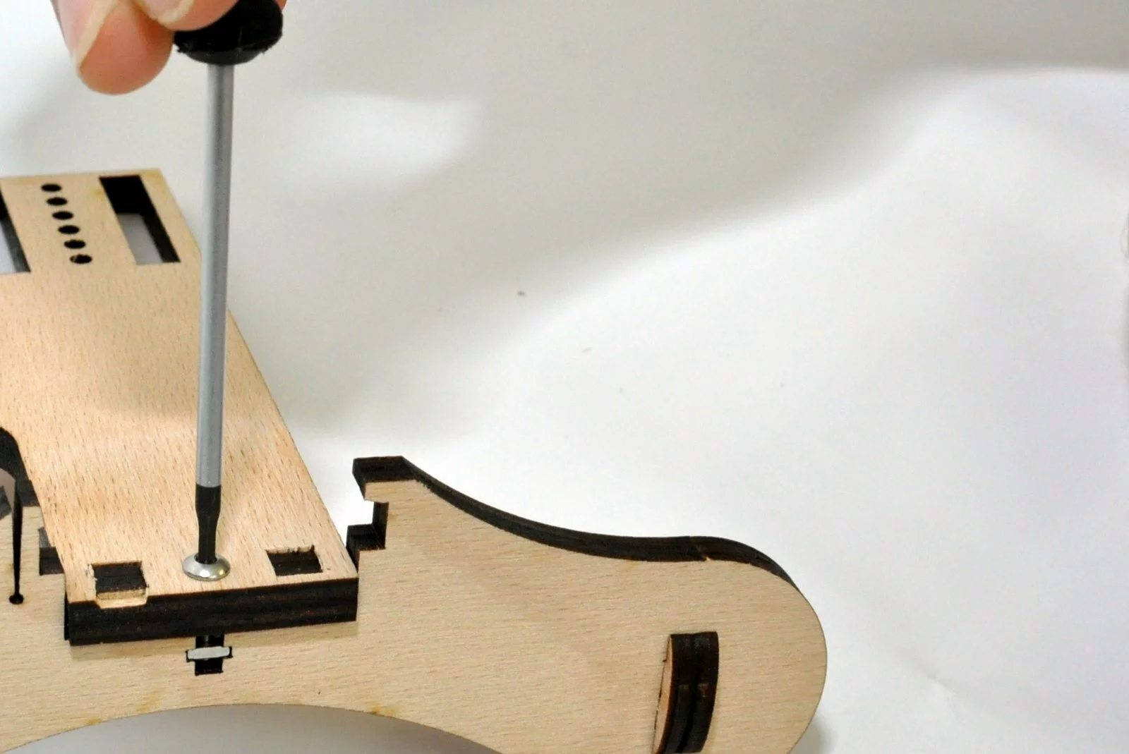
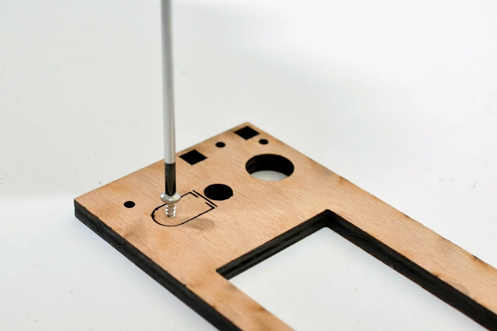
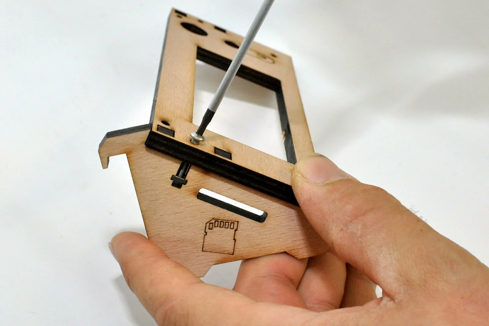
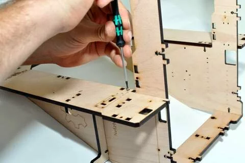
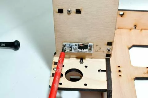
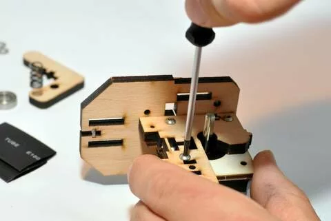
Always insert at first all the squared nuts into the wooden parts. It is easier to insert these parts from the top (the side of the parts that contain the numeration)
Screws
Wires
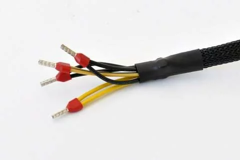
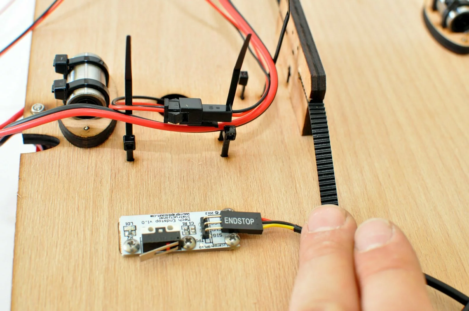
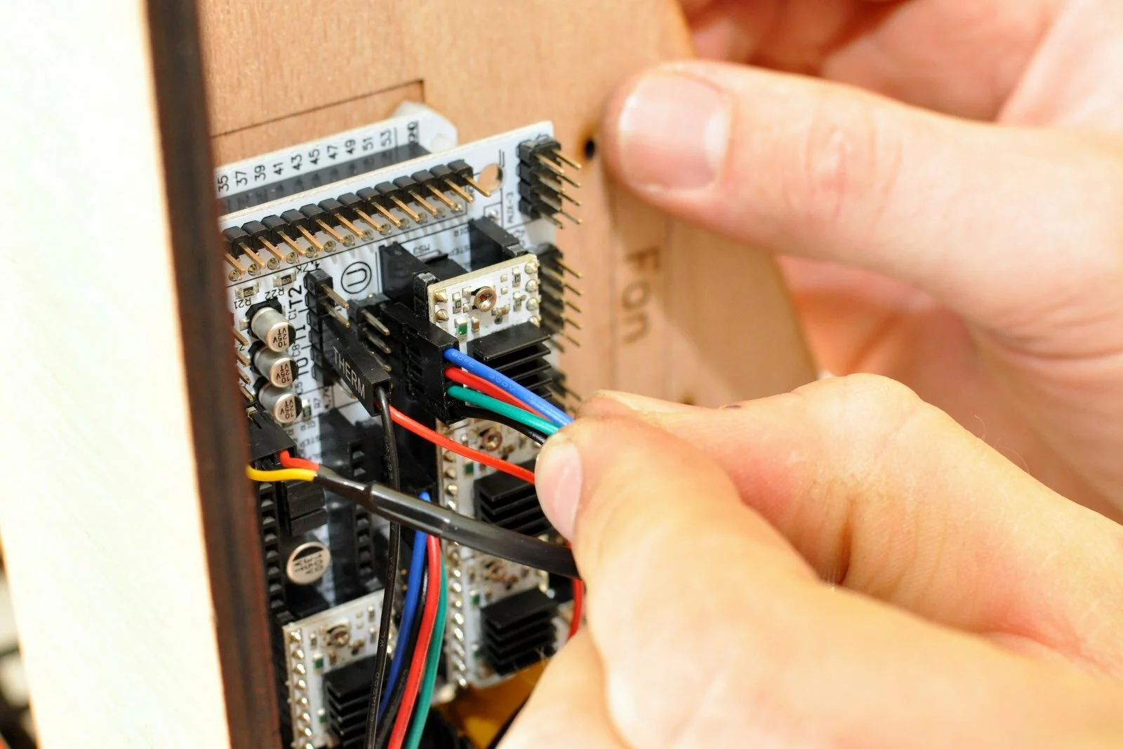
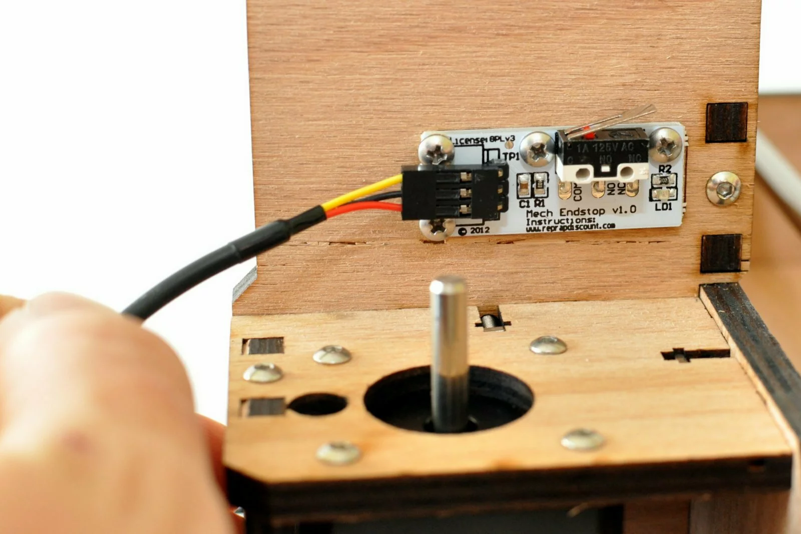
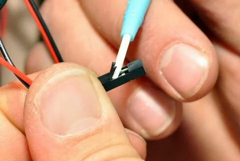
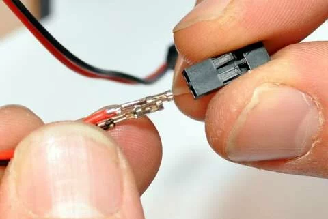
Signal Wires
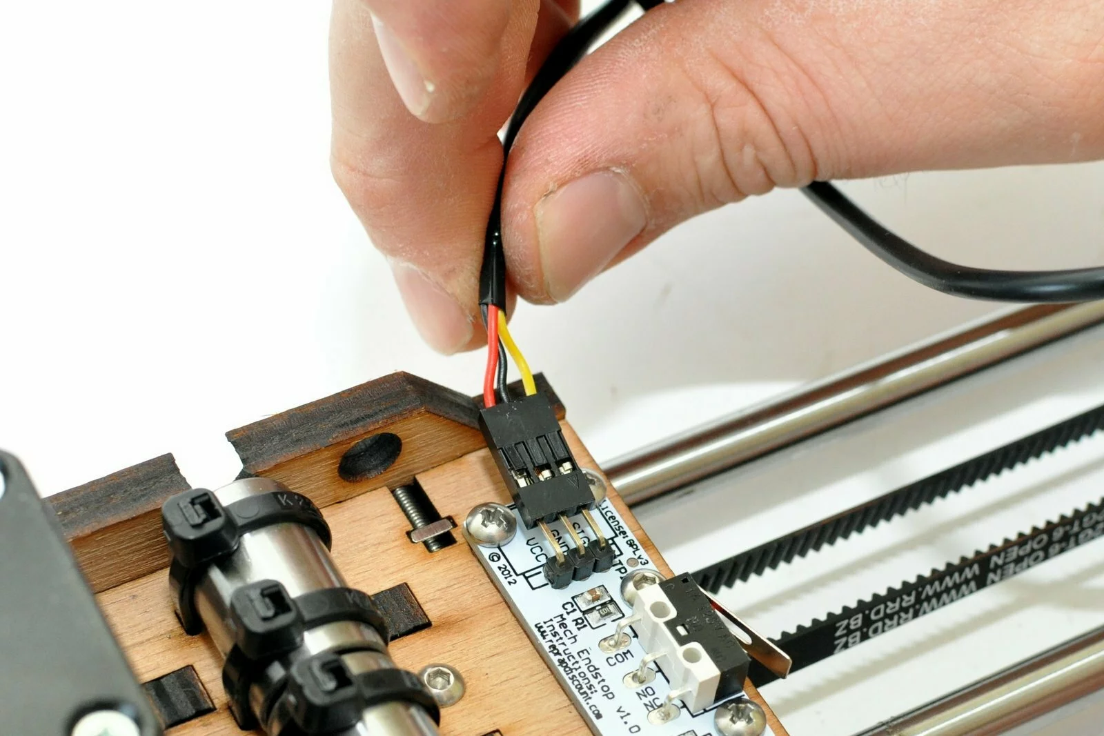
Signal wires are used for the endstops. In general they constist of a cable with three wires. You have the power supply (VCC – red wire) the ground wire (ground – black wire) and the signal cable (signal – blue wire or yellow wire – this may change from batch to batch). When plugging in the cables please make sure that you connect the plugs in the correct way. The pins on the RAMPS board and the endstops are marked nevertheless we observed makers mixing up the pins. This results in a short circuit which will not destroy the board, nevertheless the power supply breaks down when the limit switch is triggered.
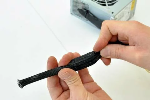
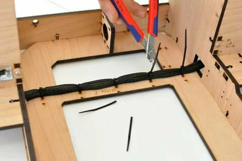
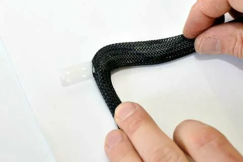
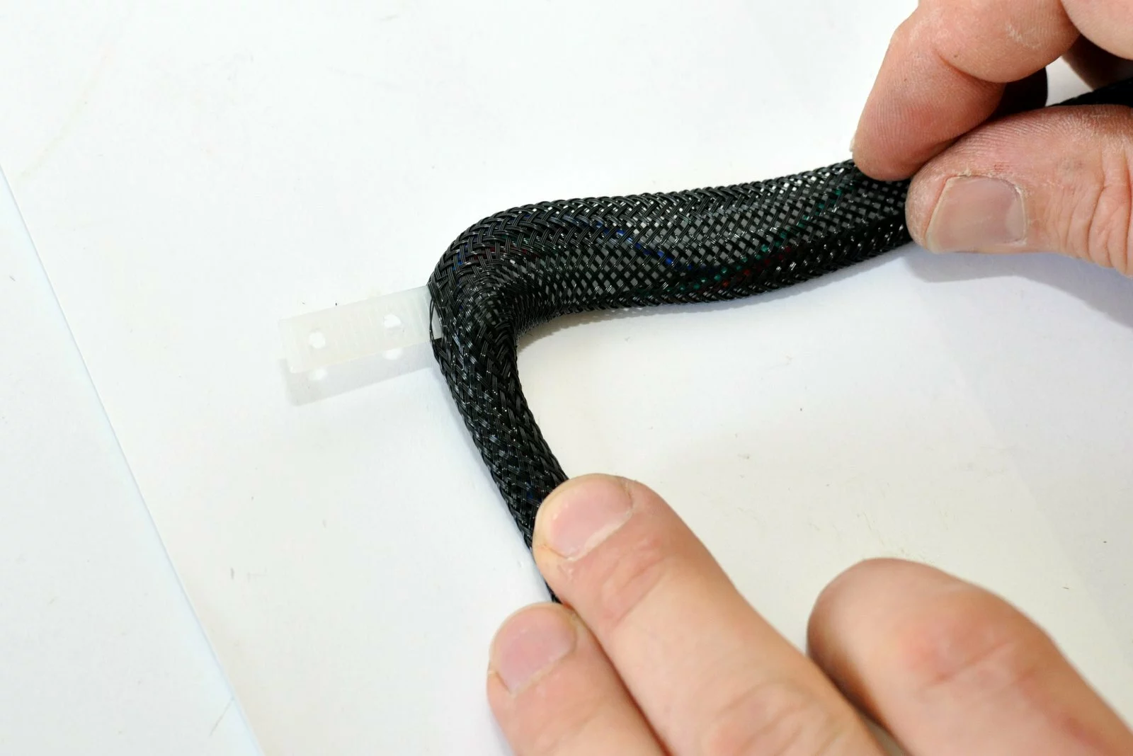
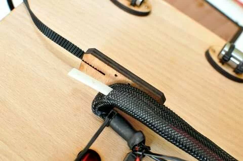
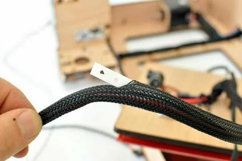
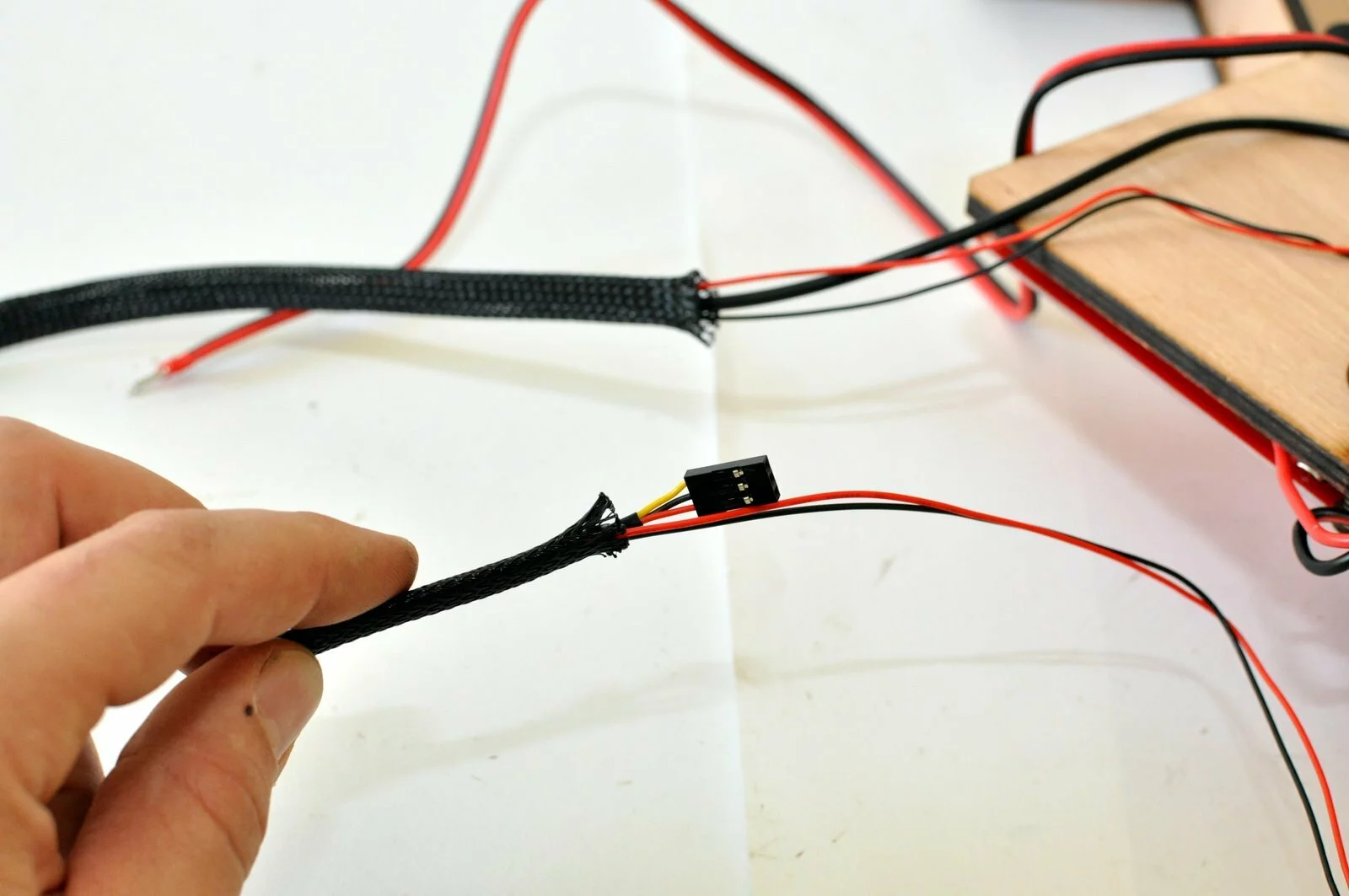
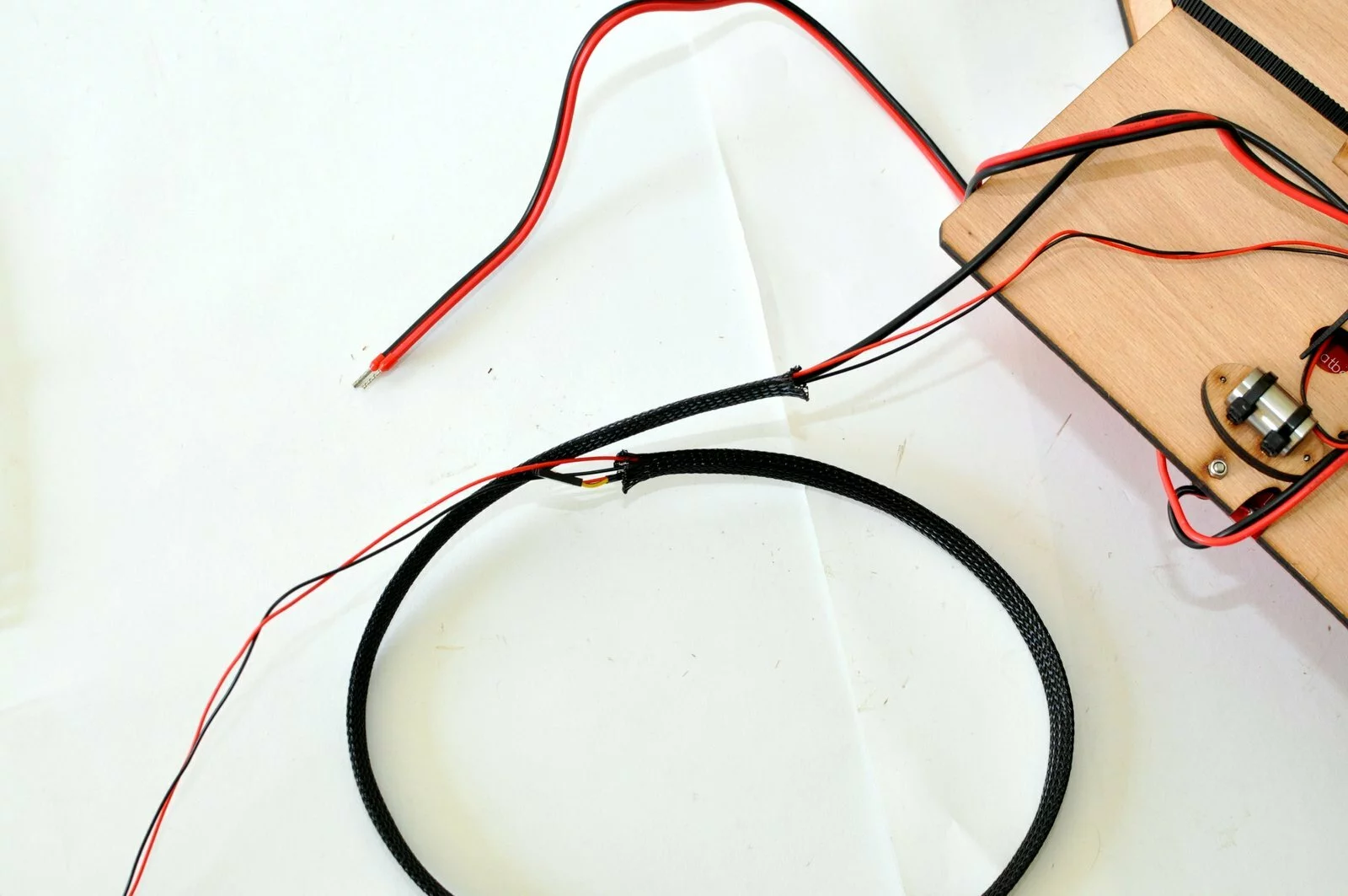
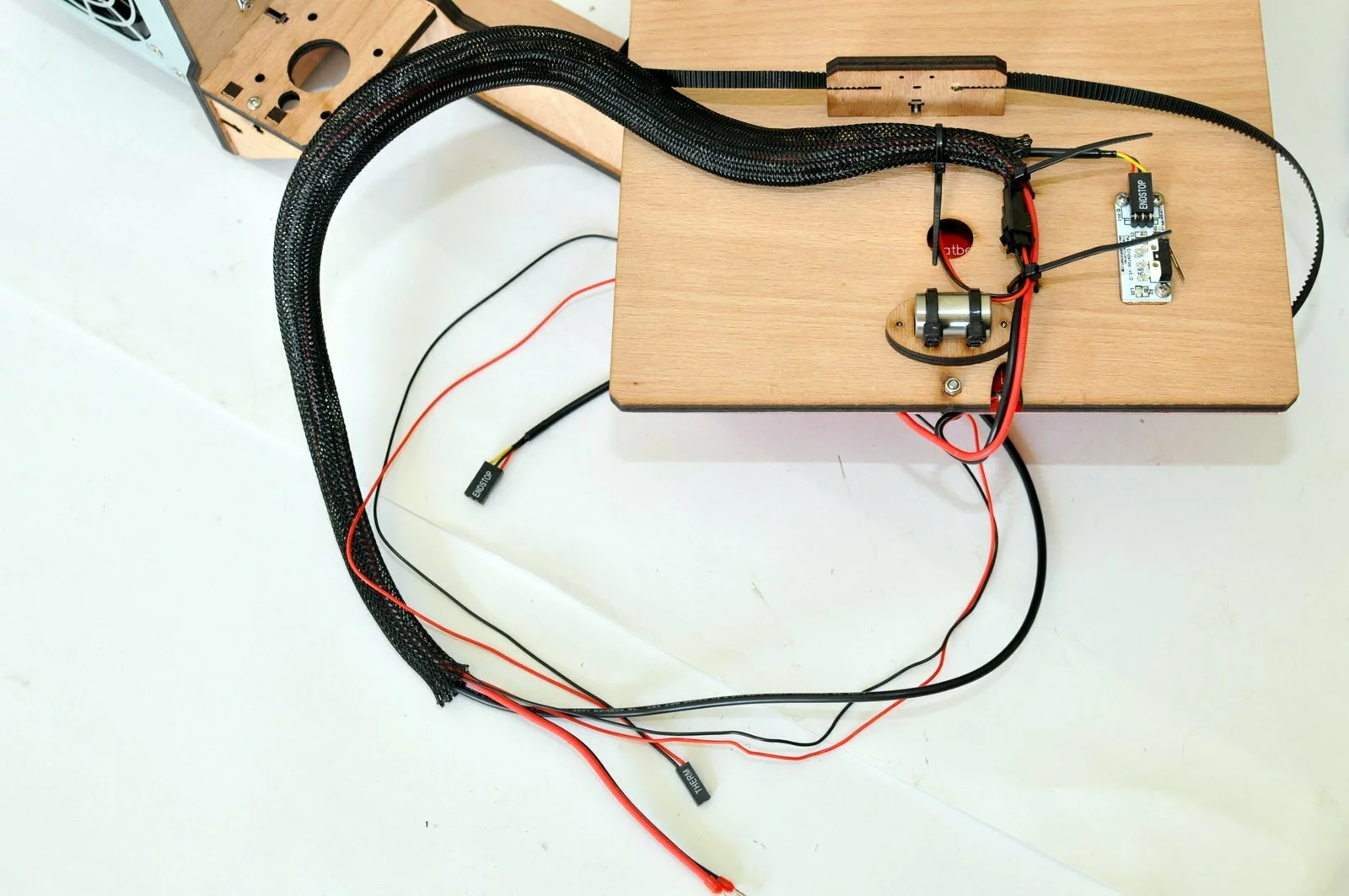
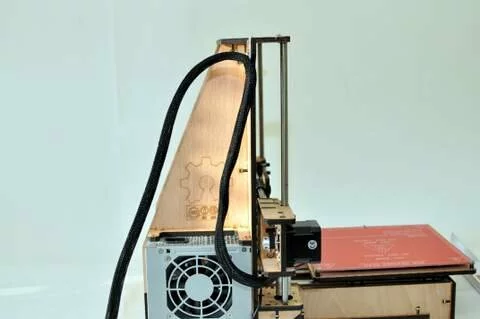
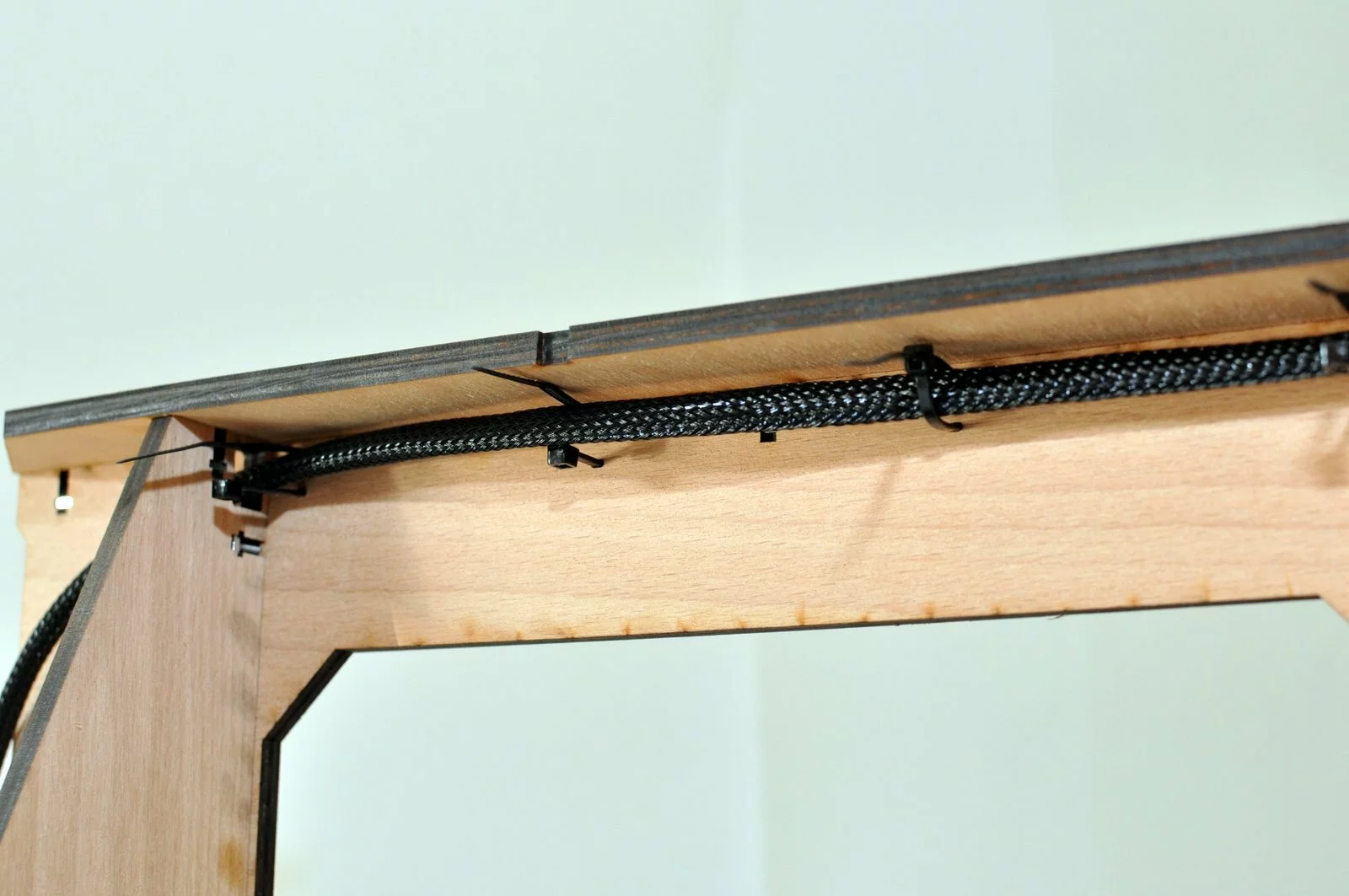
Cable sleeves
These steps are required in different sections of the build process. We are explaining these steps in detail in this section in the beginning.
-
Step
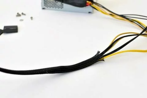
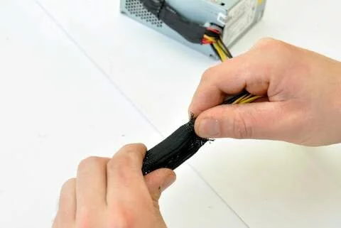
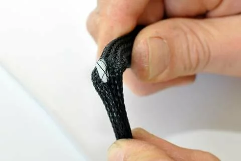
Push the cablesleeve together to increase the diameter. This makes it easier to insert the cables. -
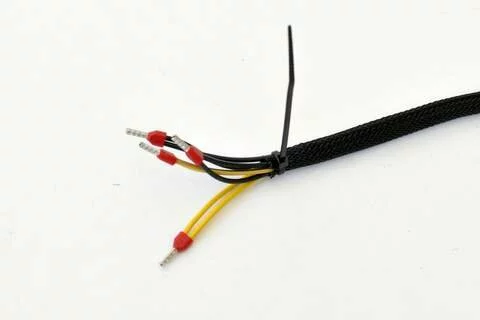
Step
-
Step
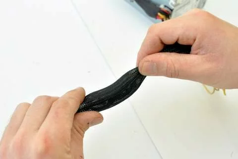
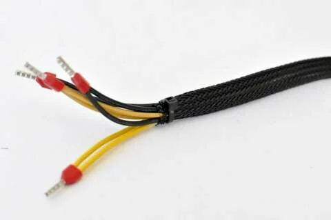
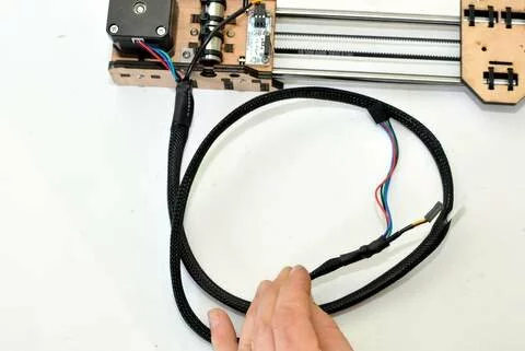
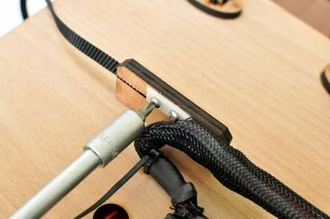
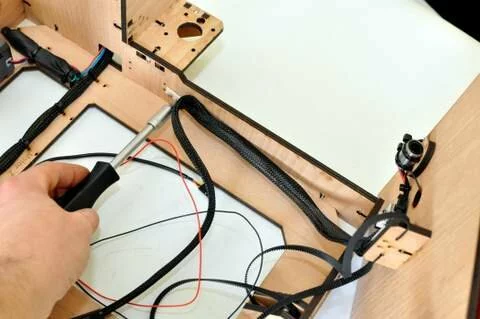
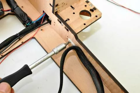
Push the sleeve together and realease it as you move it along the wires -
Step
- Step
- Step
- Step
- Step
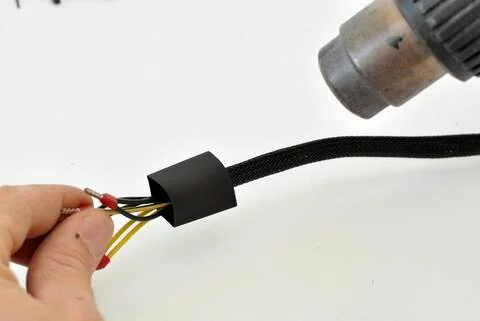
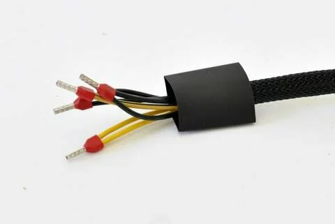
-
Step
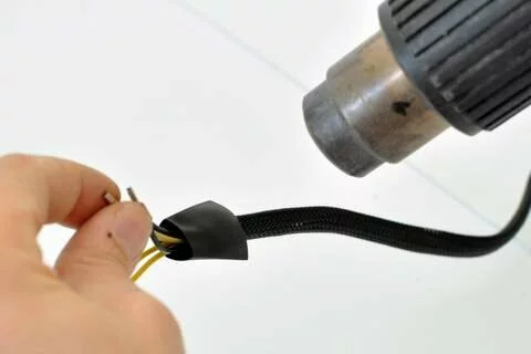
You may also use a lighter or a soldering iron to shrink the tube -
Step
Belts
Mounting
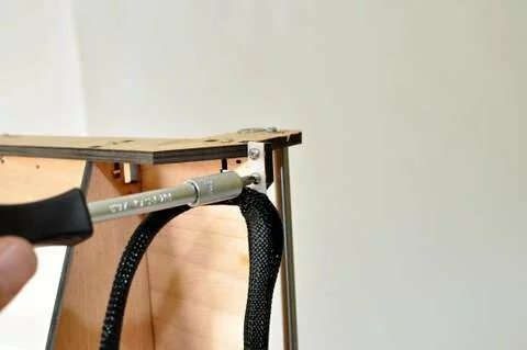
Tensioning
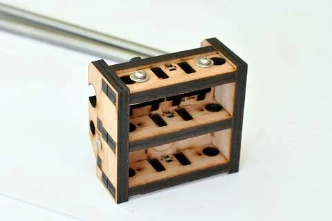
Step 01
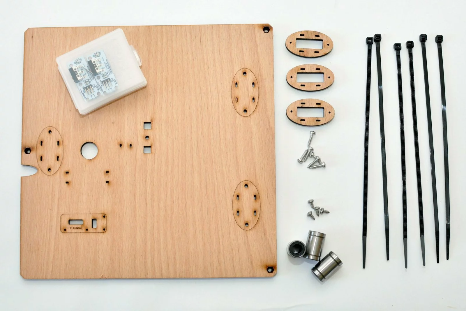
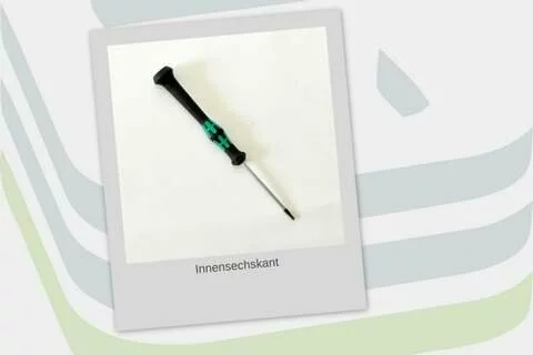
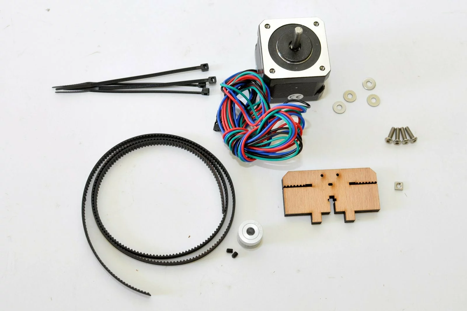
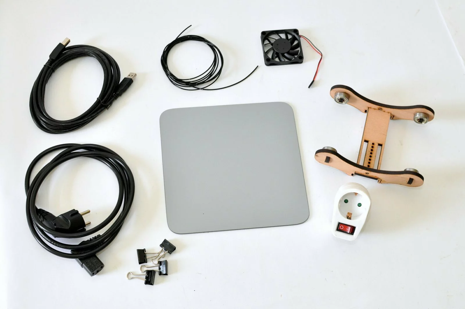
Tools

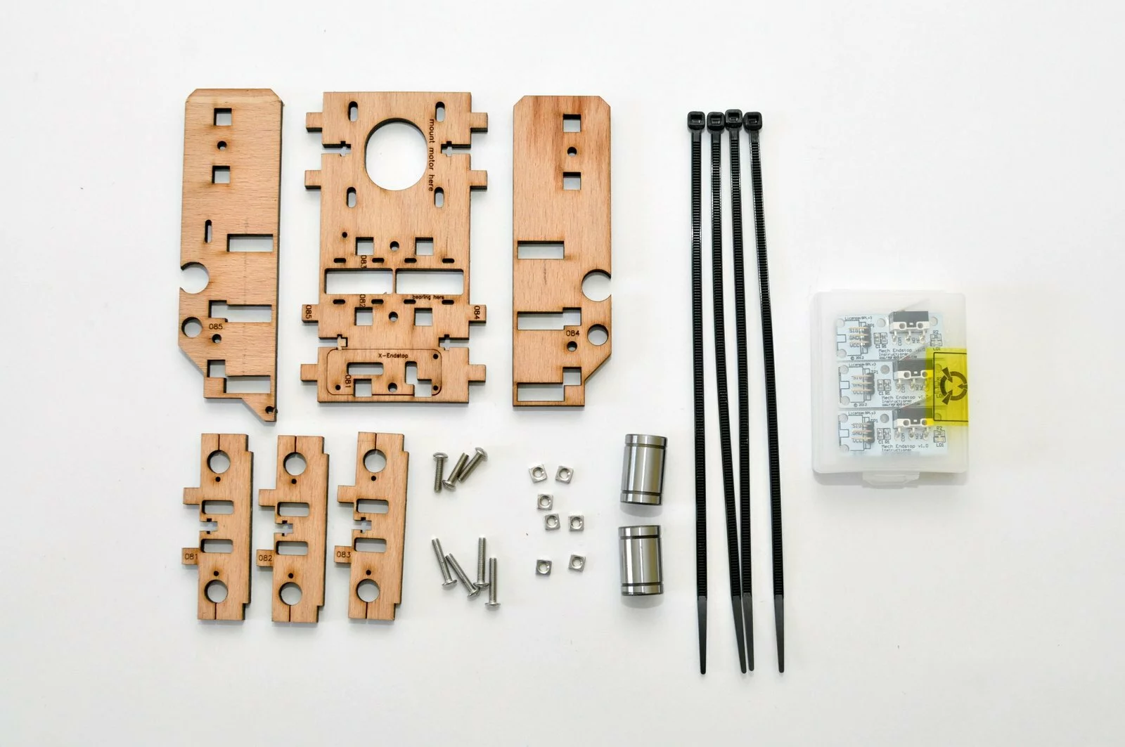
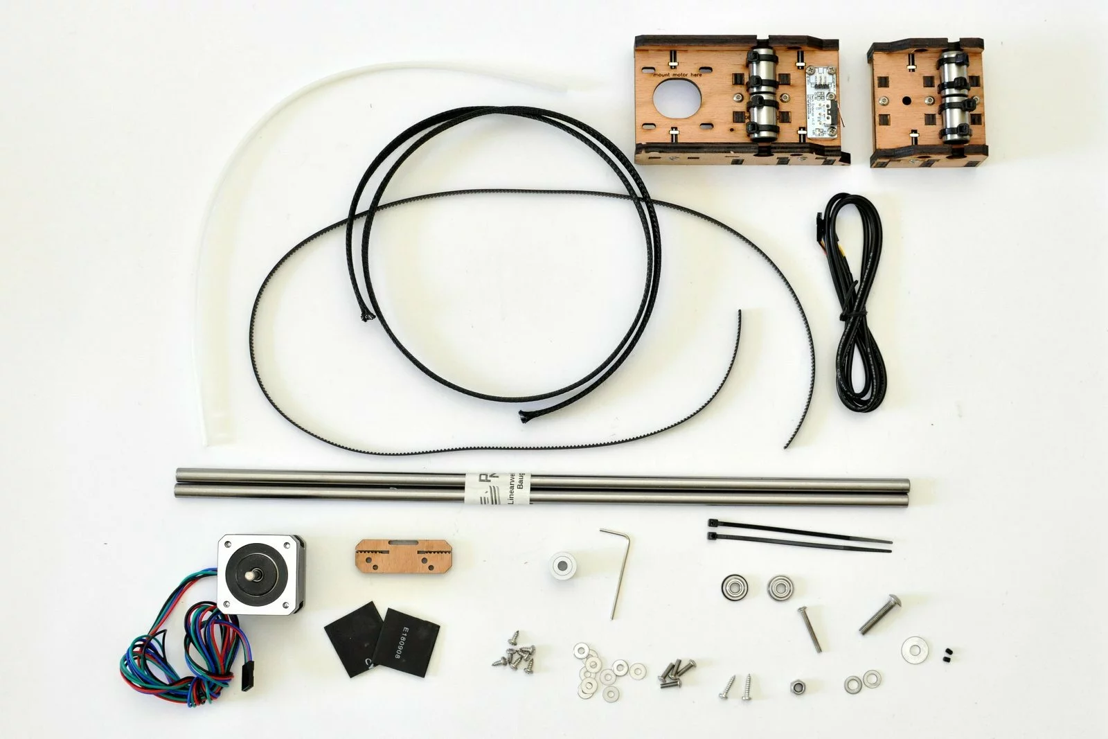
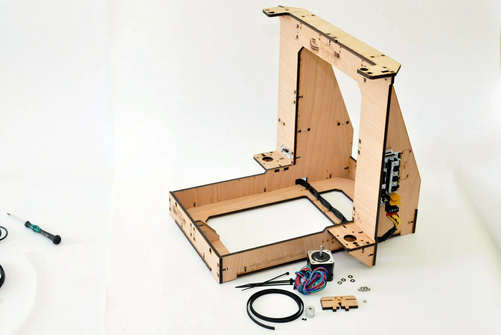
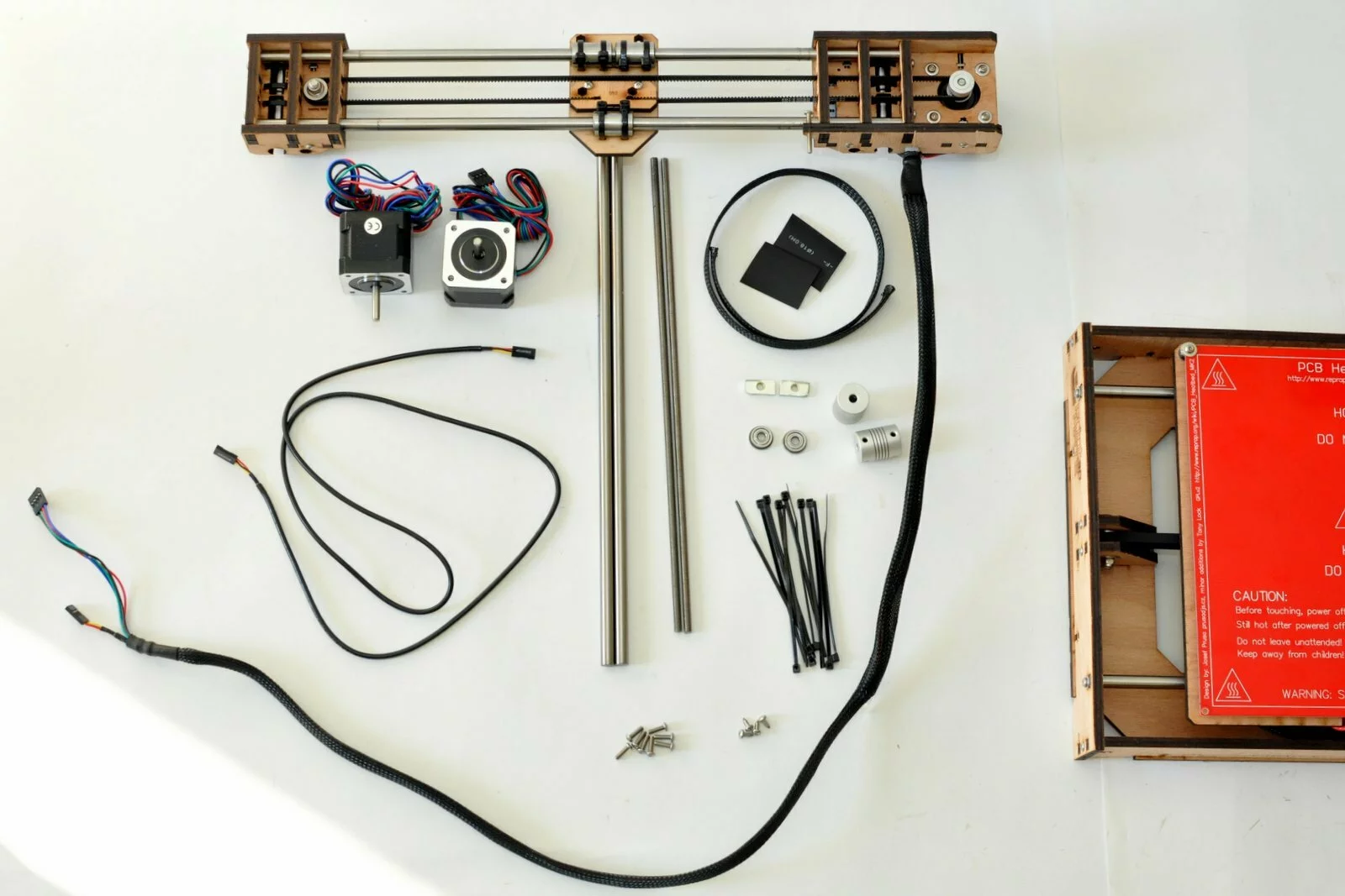
Parts
Video
Steps
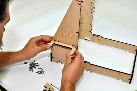
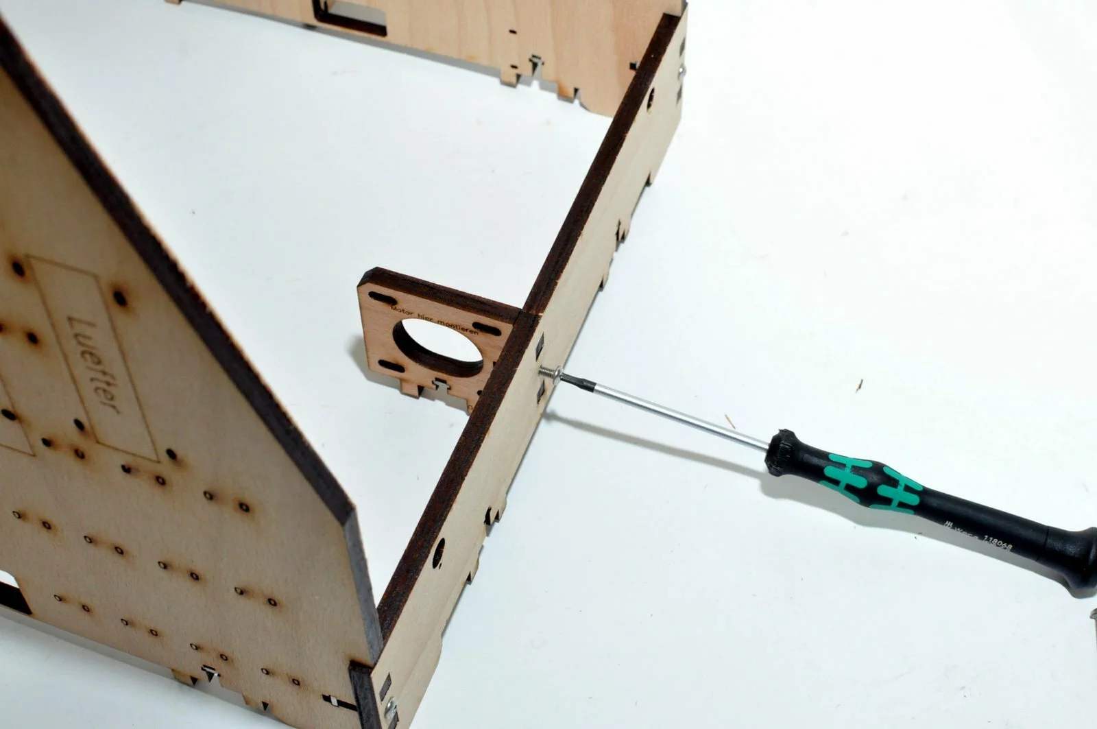
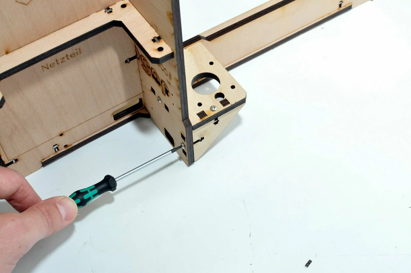
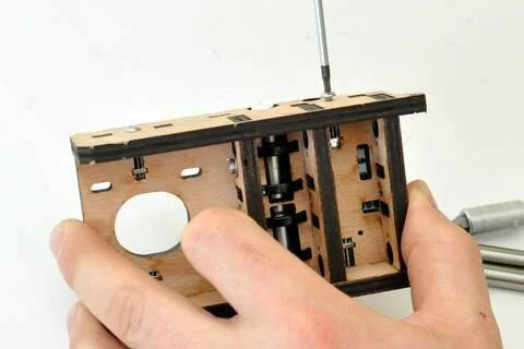
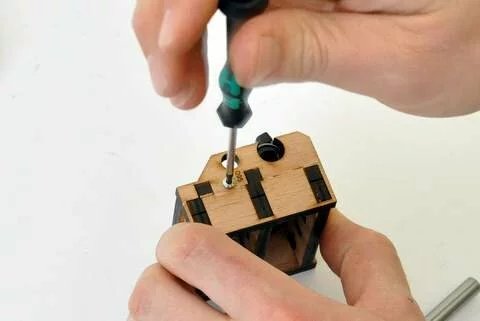
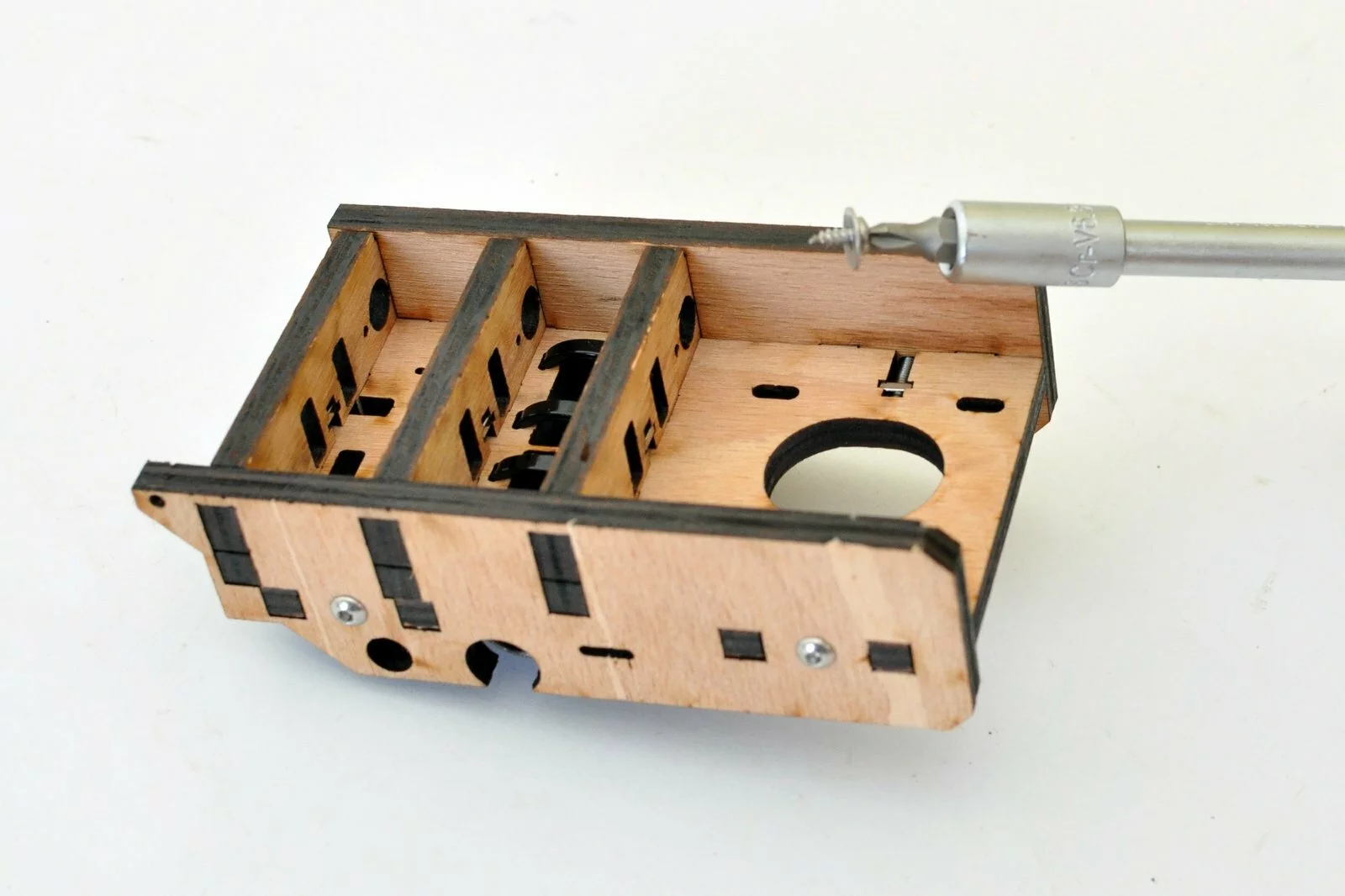
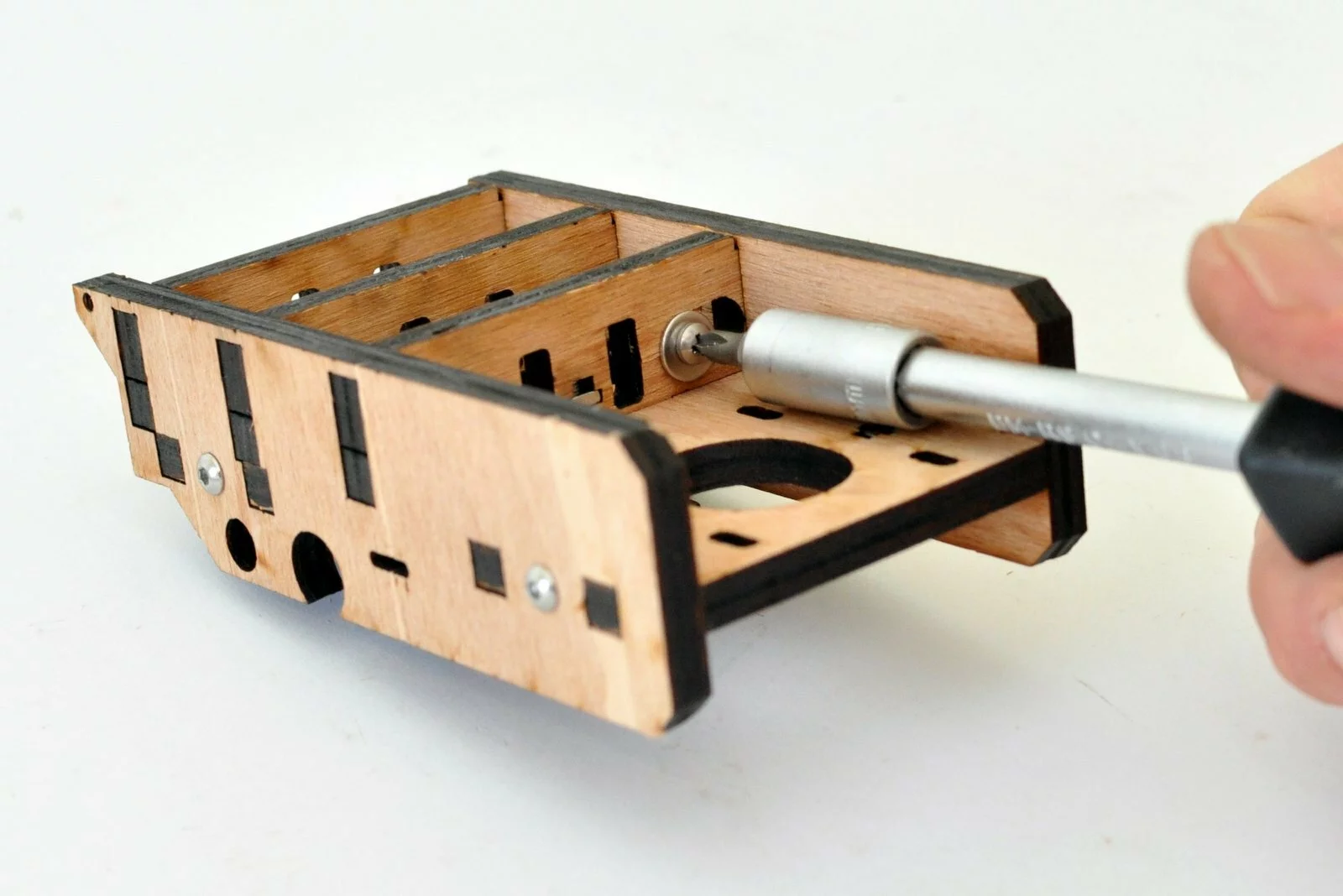
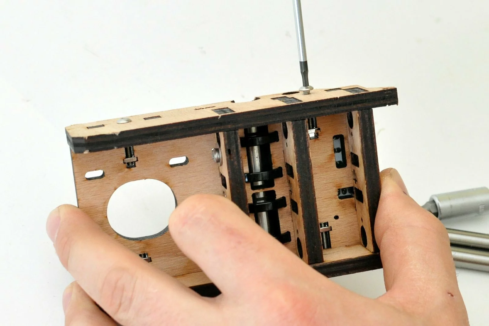
- Step
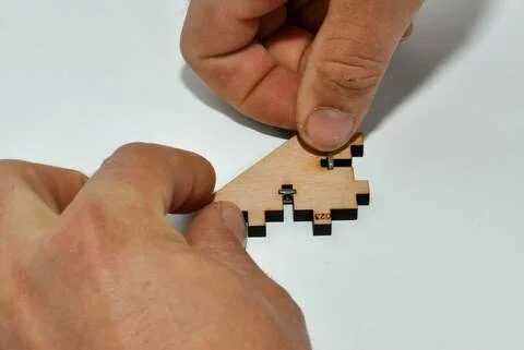
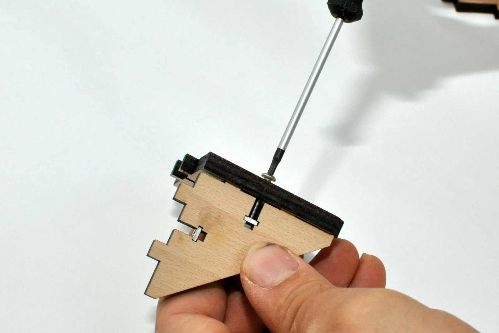
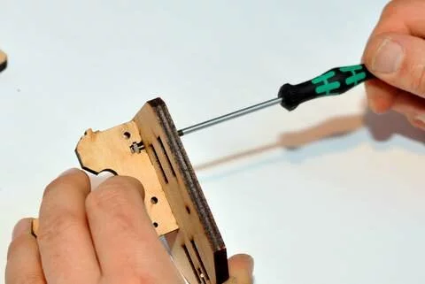
Insert all the squared nuts at first. - Step
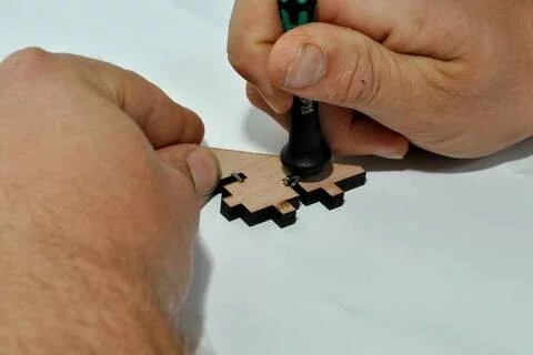
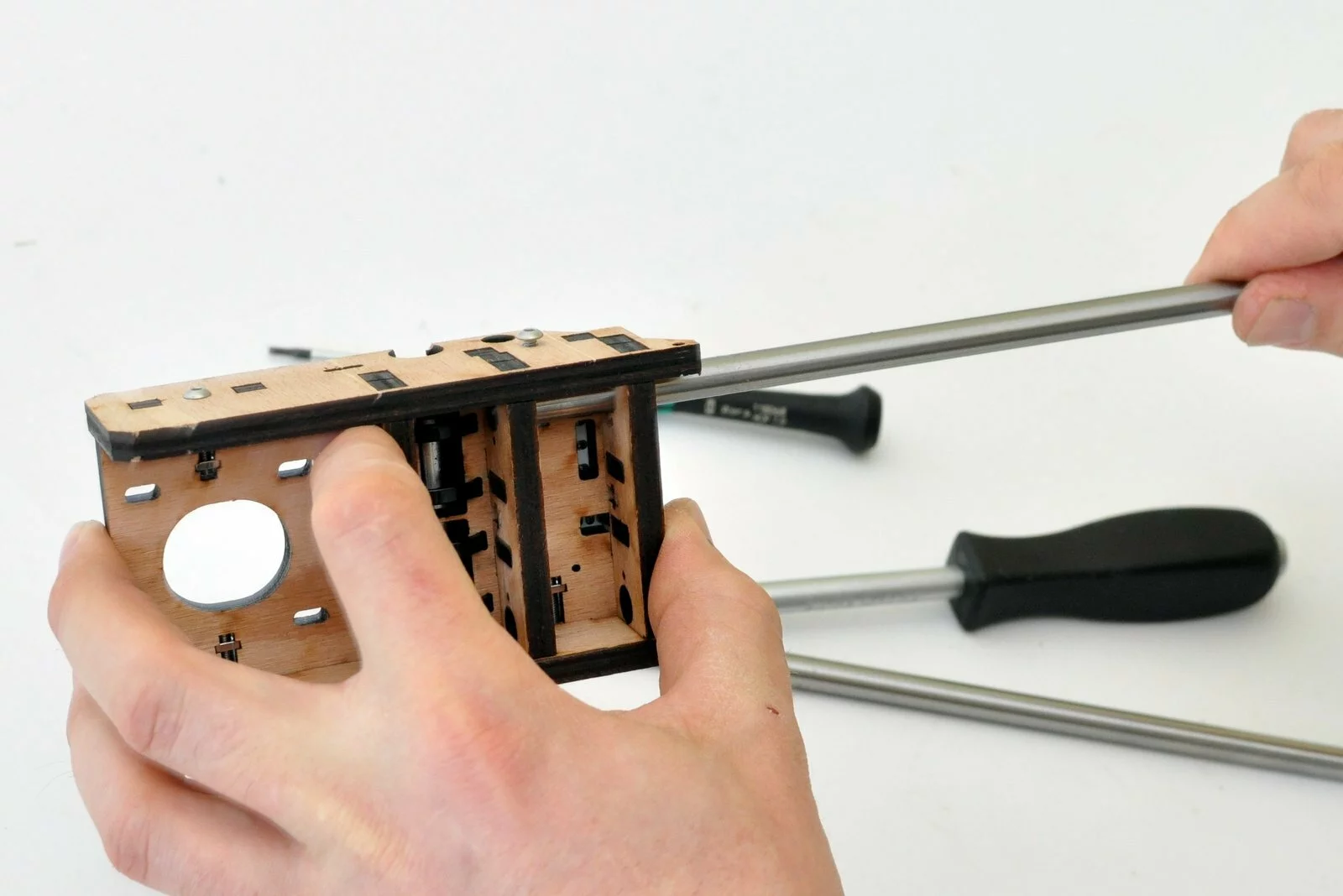
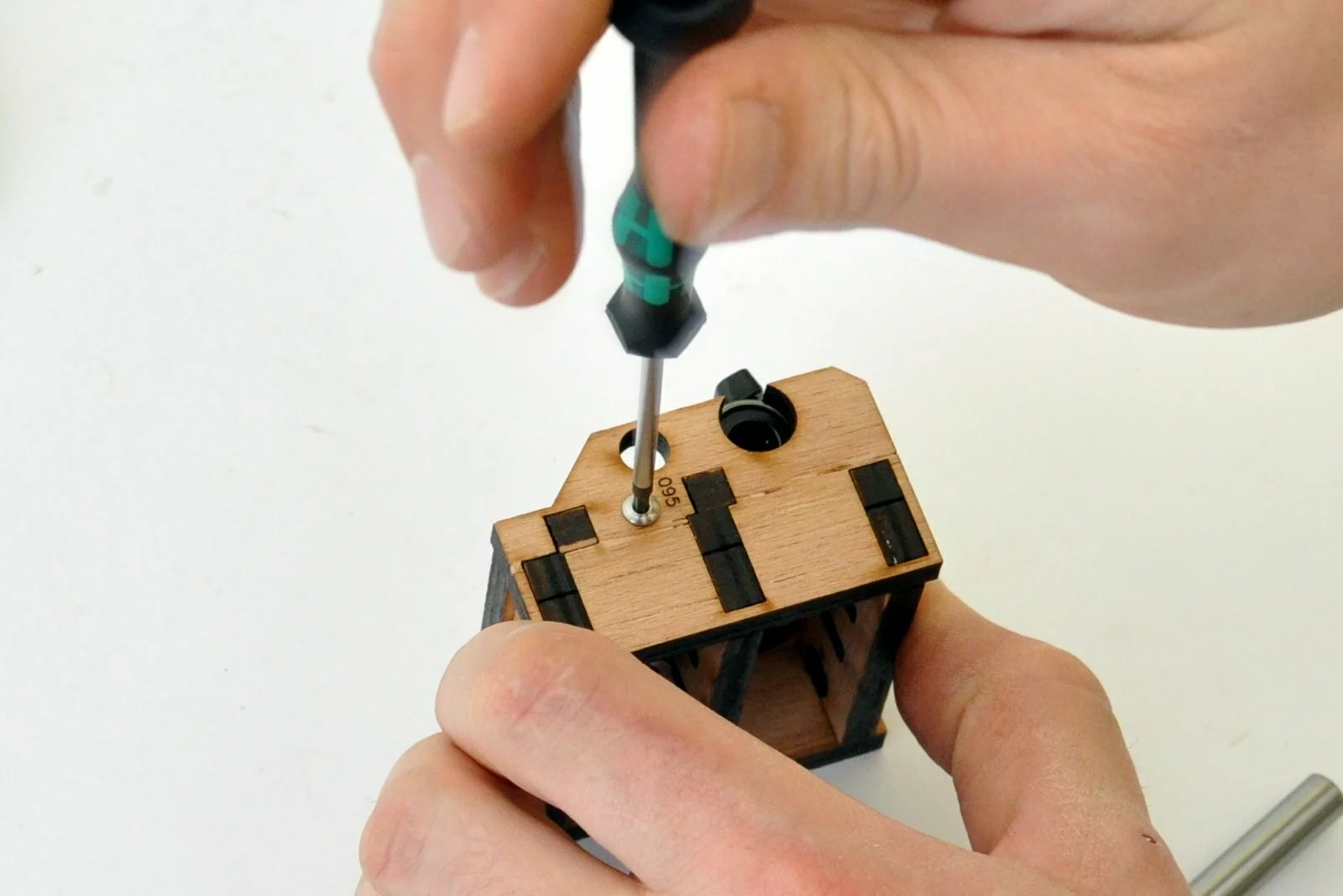
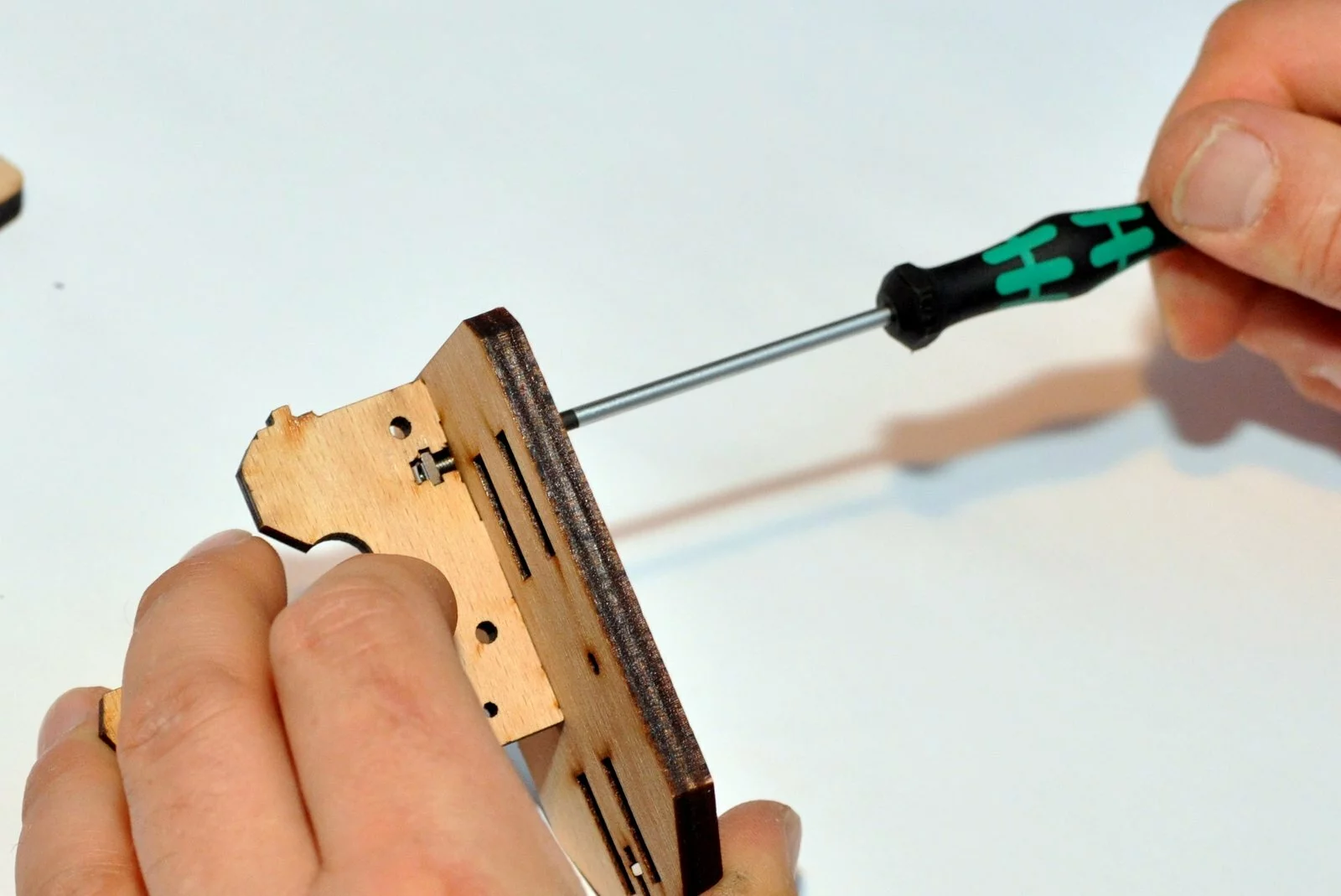
You may need to use the end of your screwdriver in order to mount the squared nuts. - Step
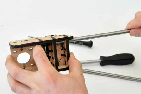
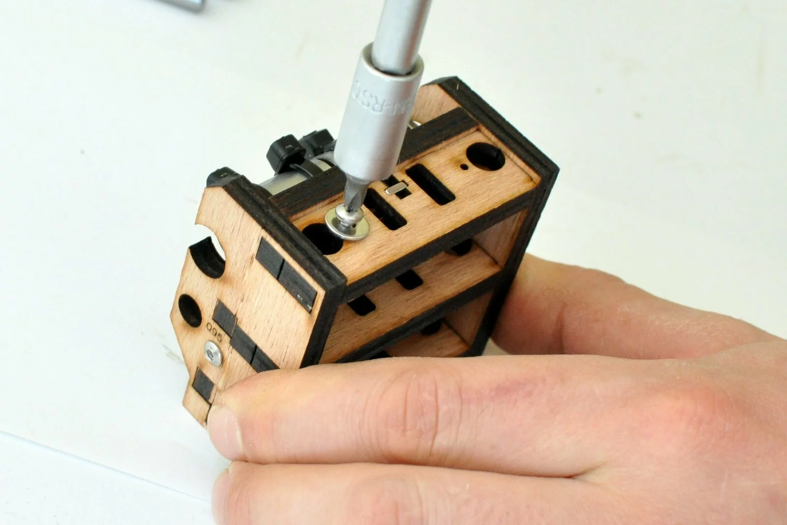
- Step
- Step


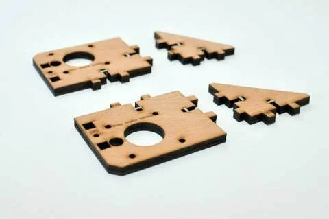
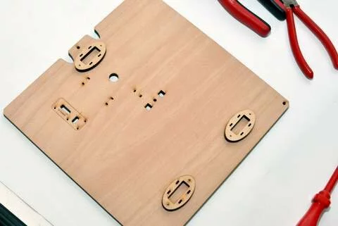
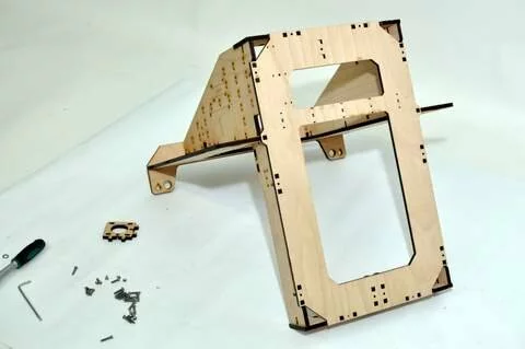
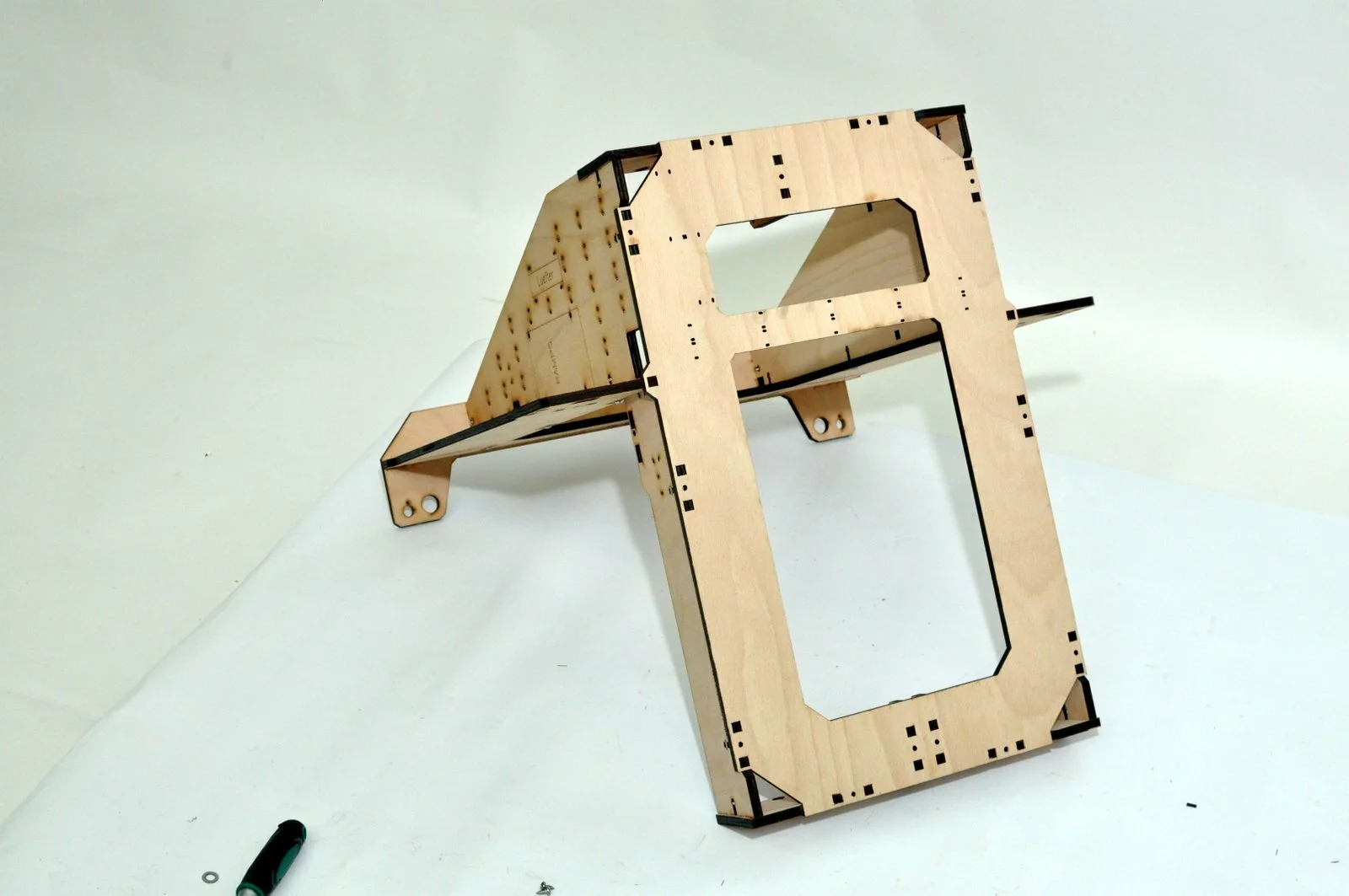
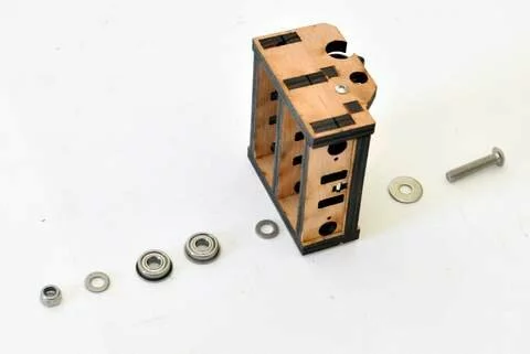
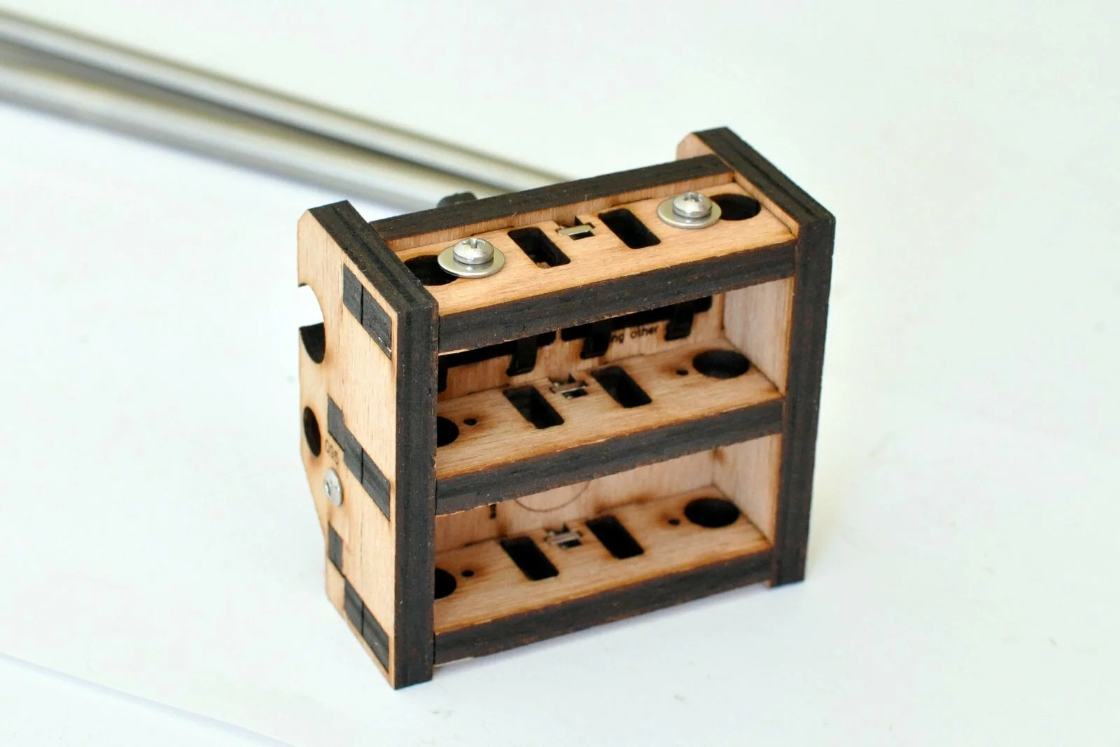
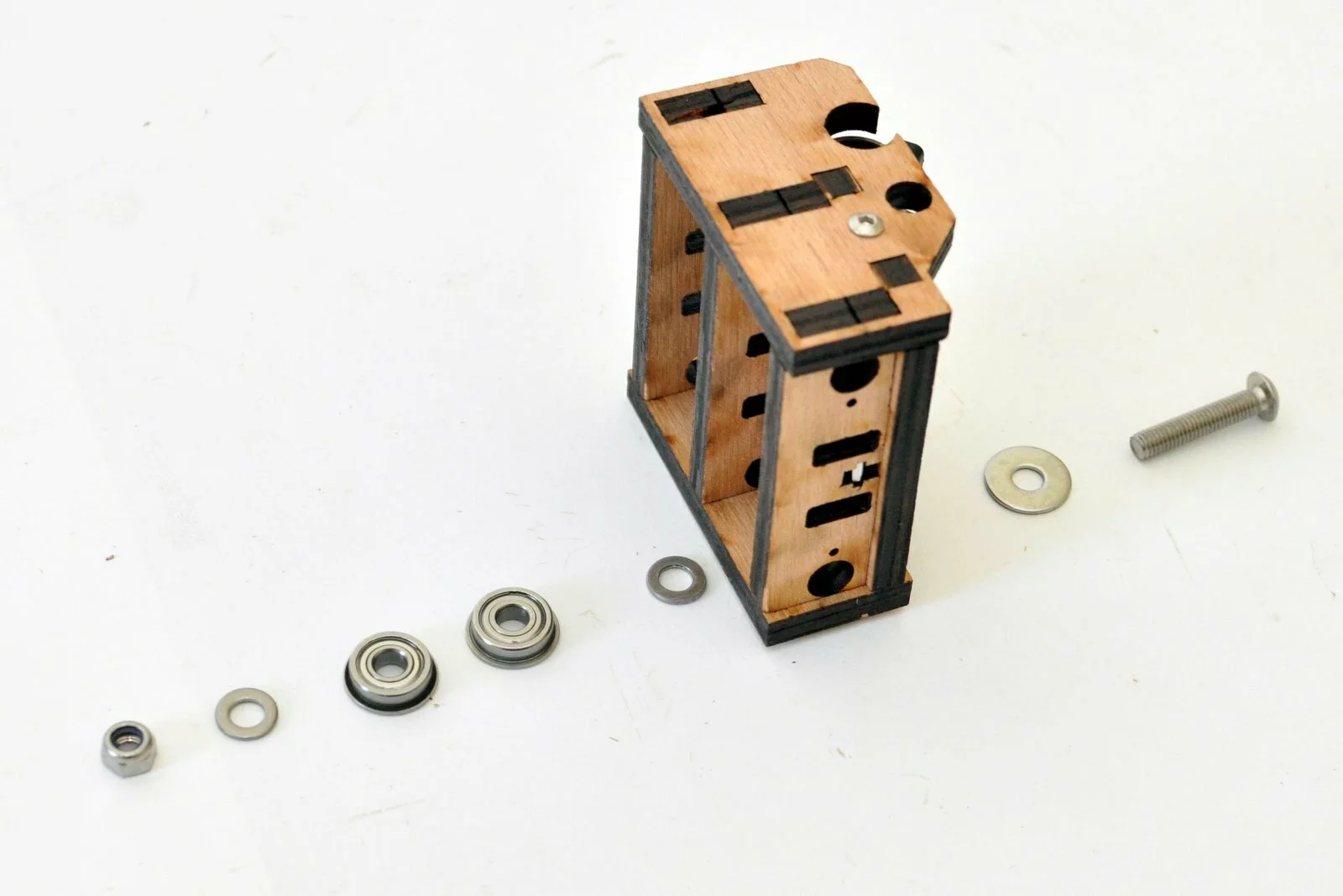
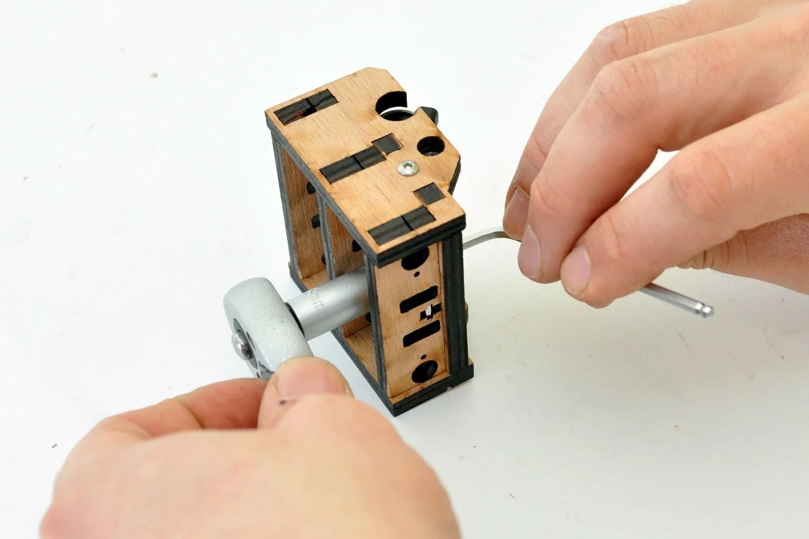
Result
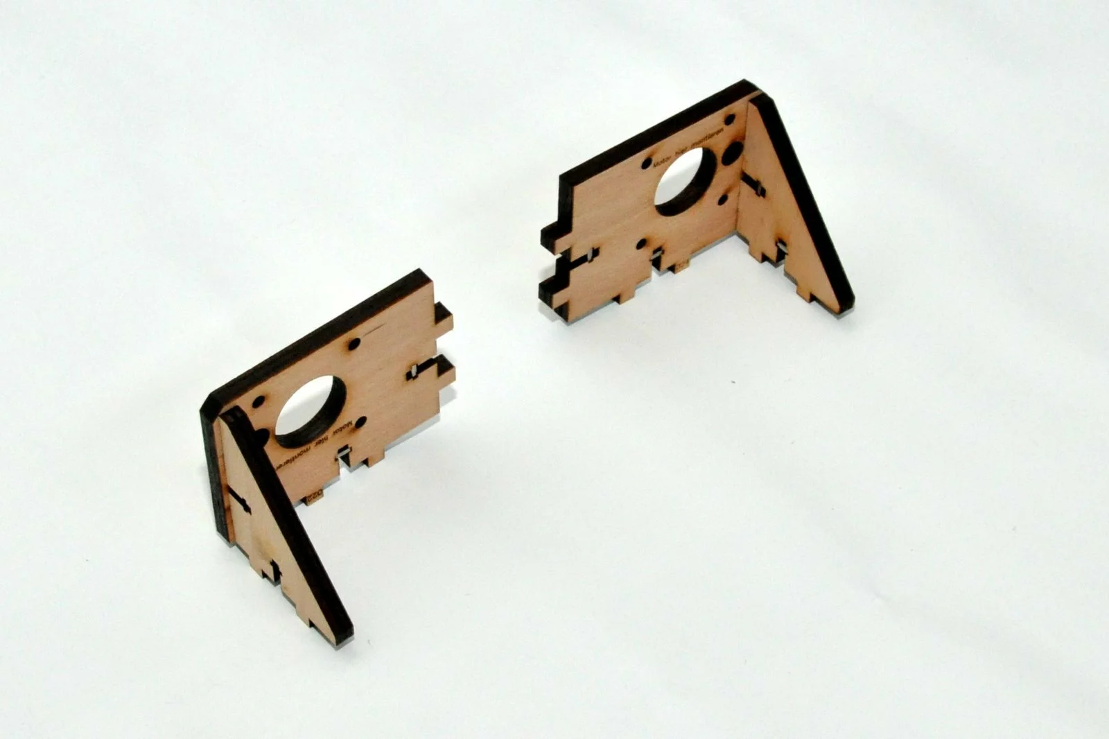
The parts can be put to the side as they will be mounted on the mainframe later.
Step 02
Tools
Parts
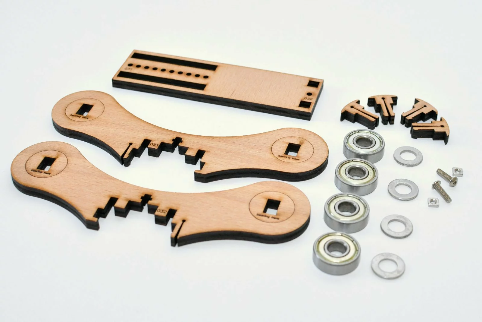
Video

Steps
- Step
- Step
-
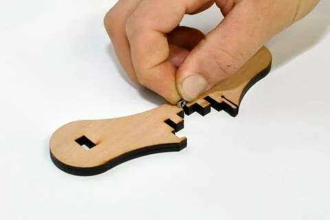
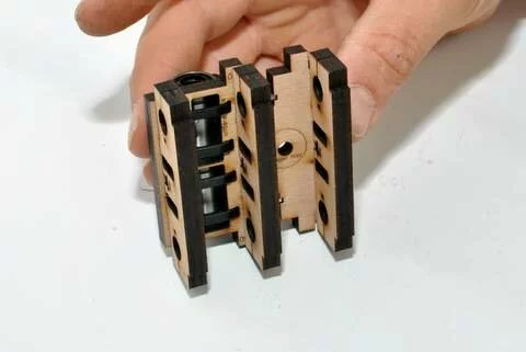
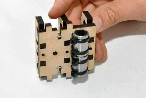
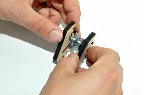
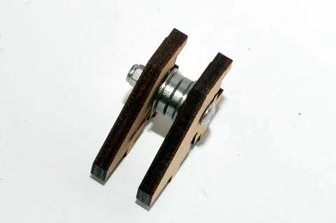
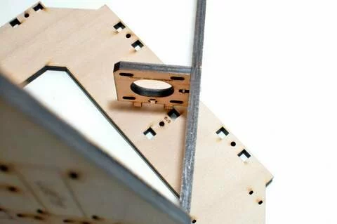
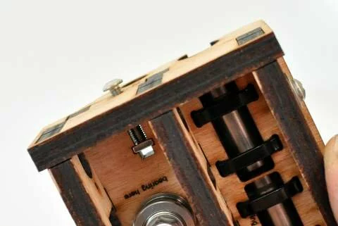
Step
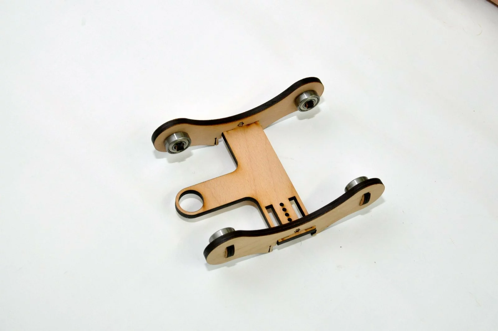
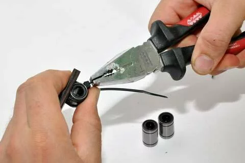
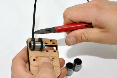
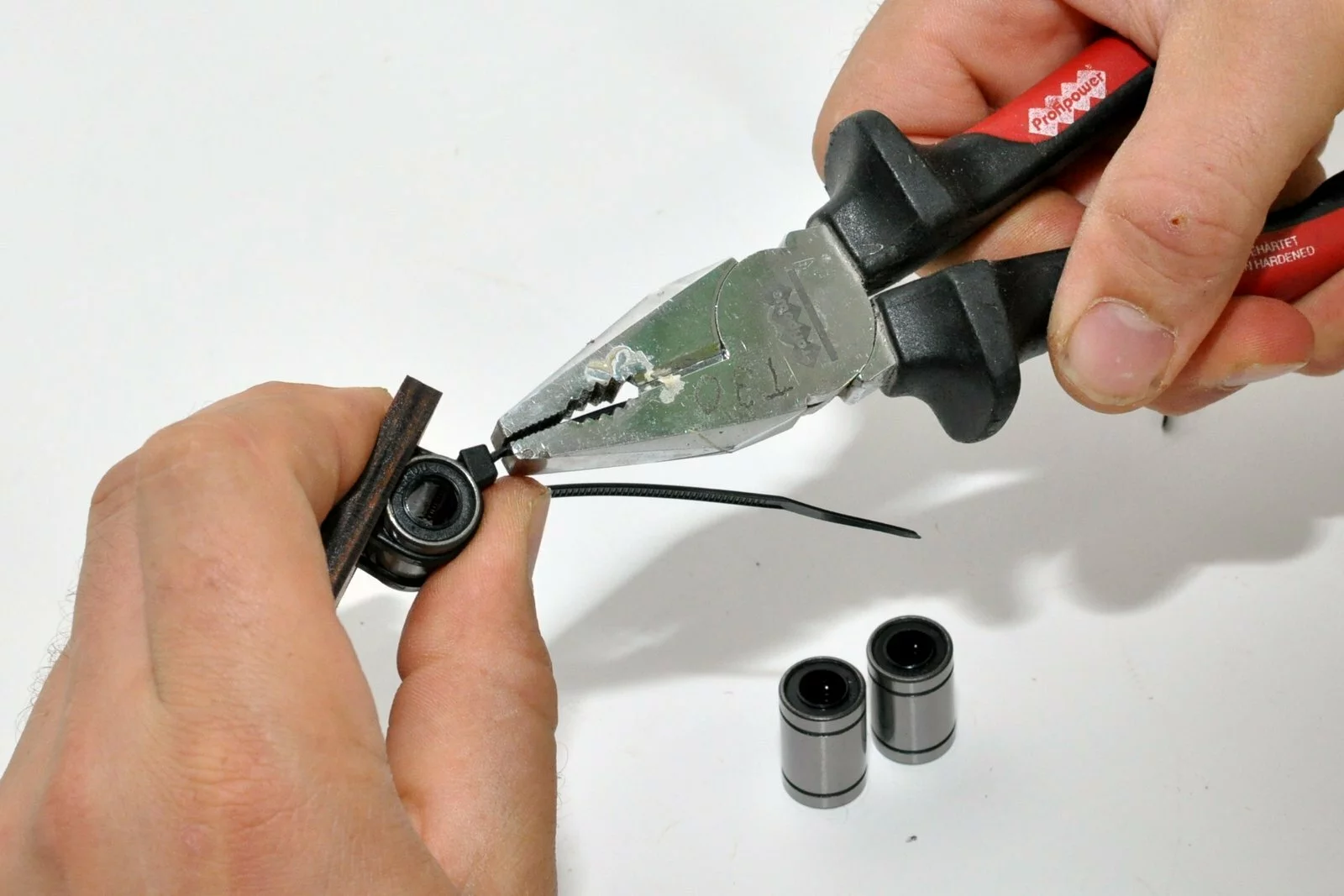
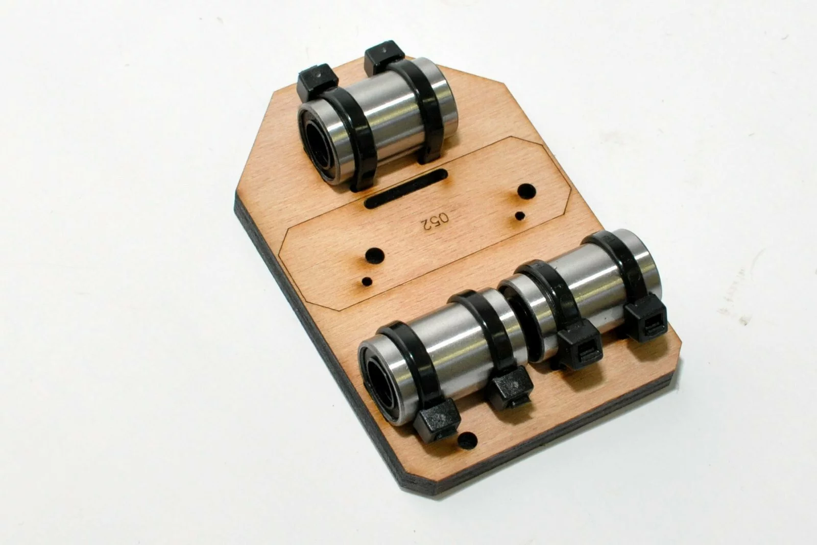
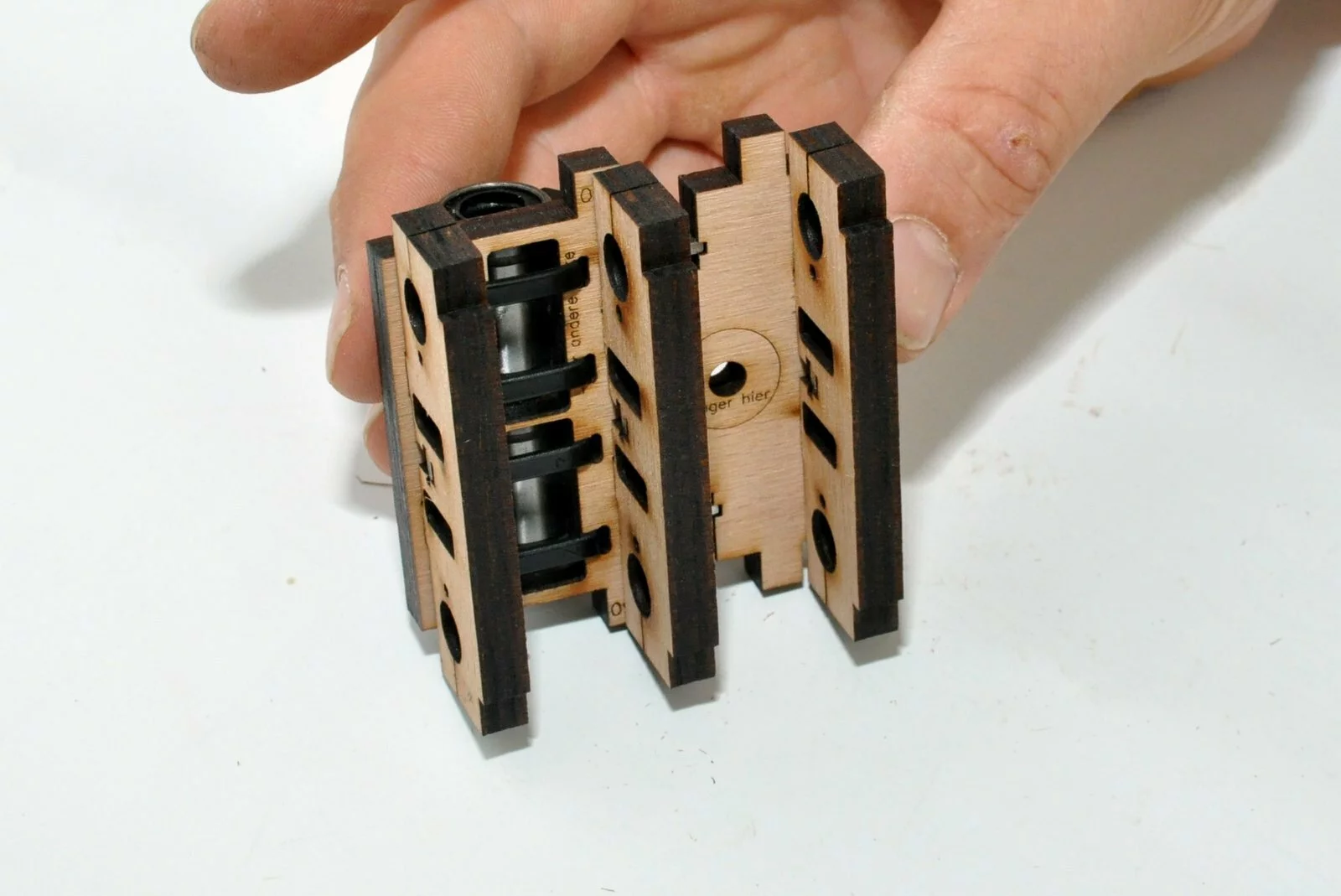
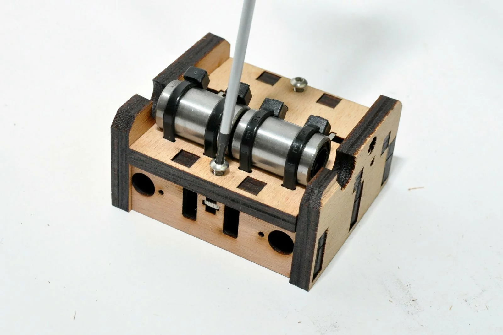
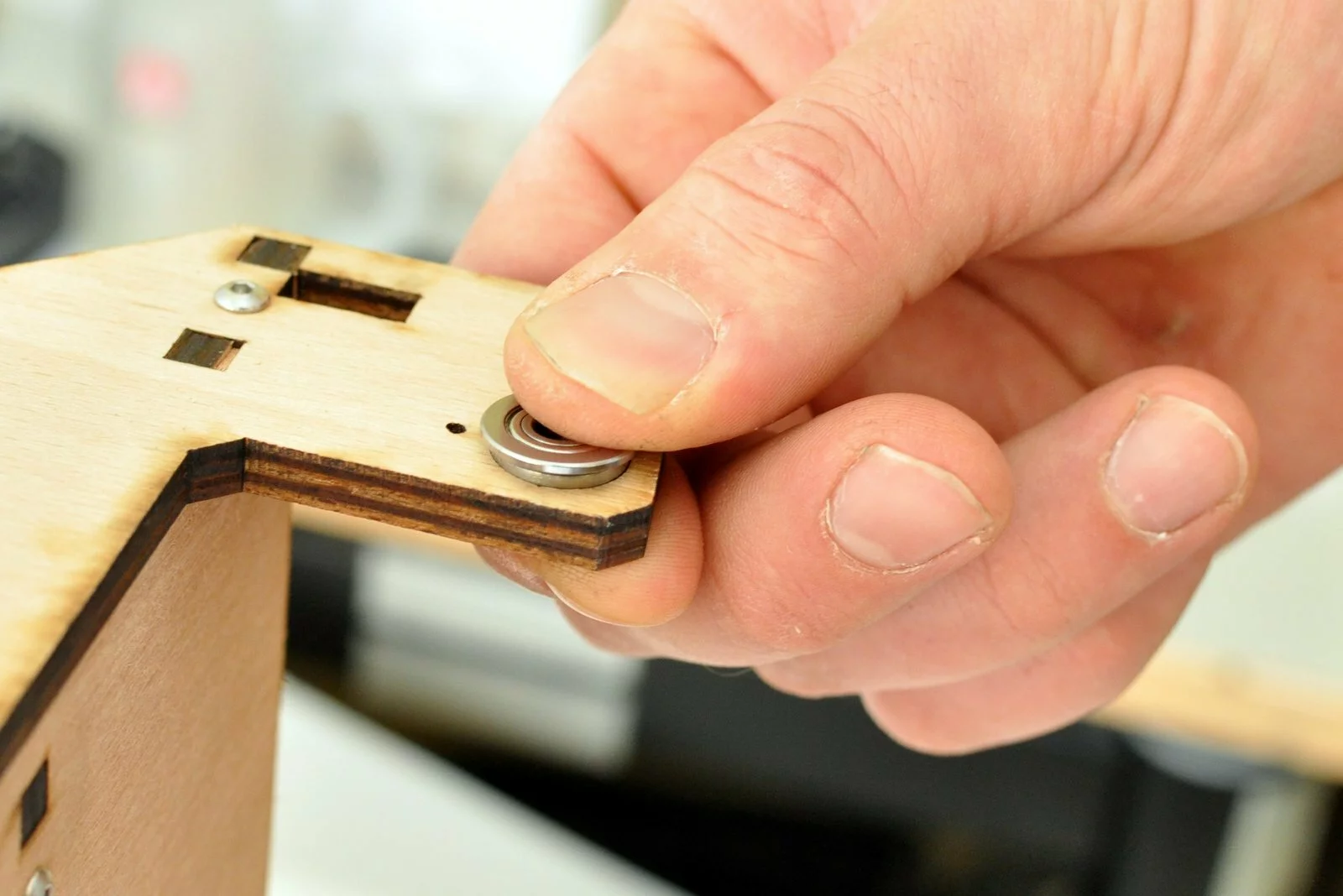
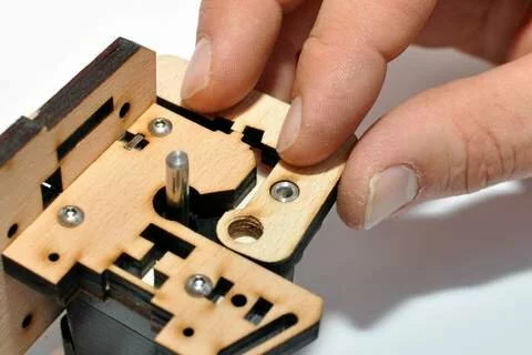
The bearing holders are inserted from the backside (the side of the part that doesn’t contain the numeration) -
Step
- Step
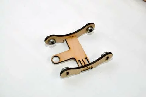


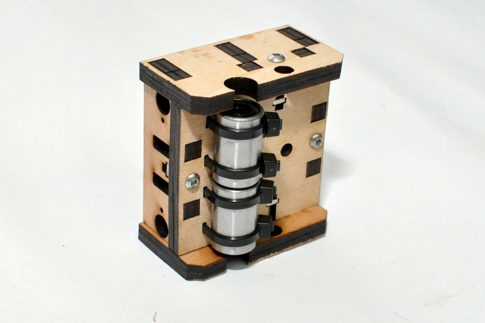
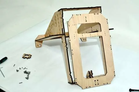
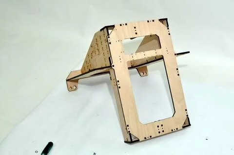
Result
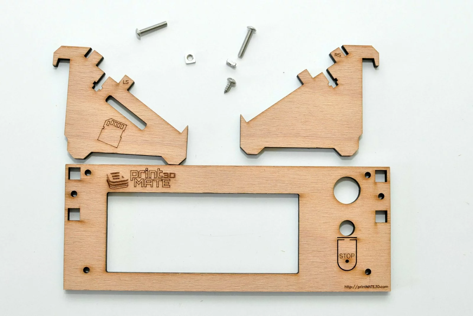
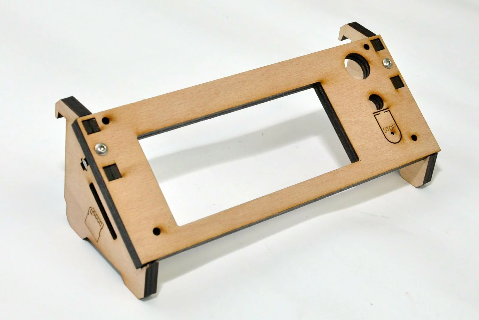
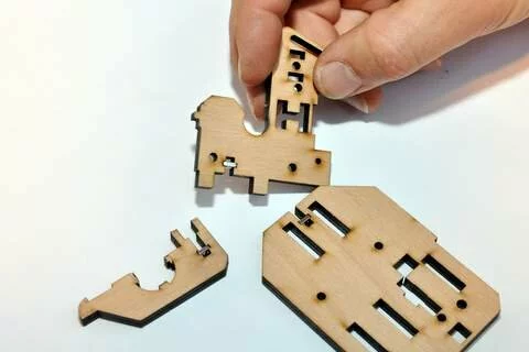
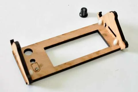
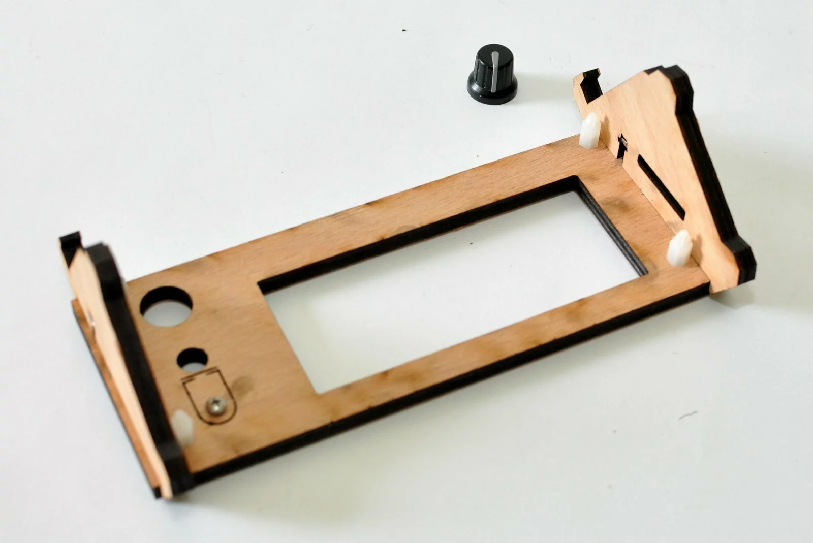
Step 03
Tools
Parts
Video

Steps
- Step

- Step
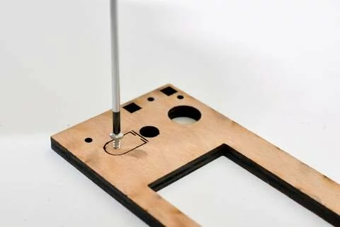
-
Step
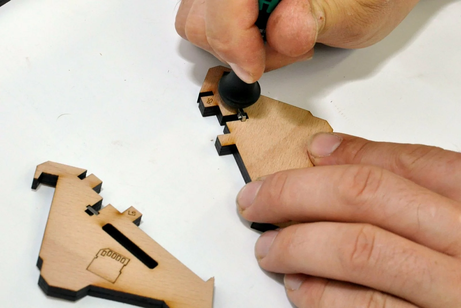
The connections are not numbered but are marked as left side and right side (ls and rs) -
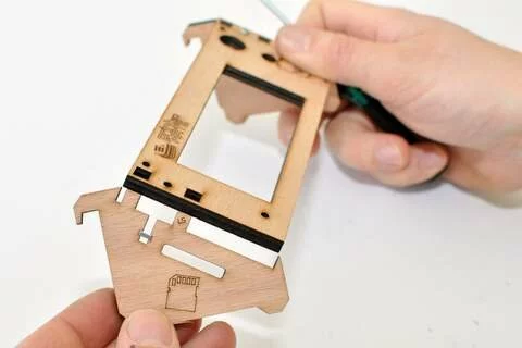
Step

- Step
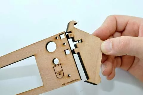
- Step


Result
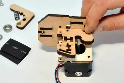
Step 04
Tools

Parts

Video

Steps
- Step
- Step
- Step
- Step

Result
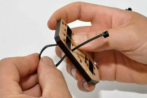
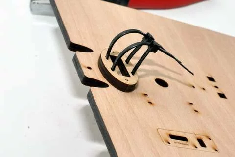
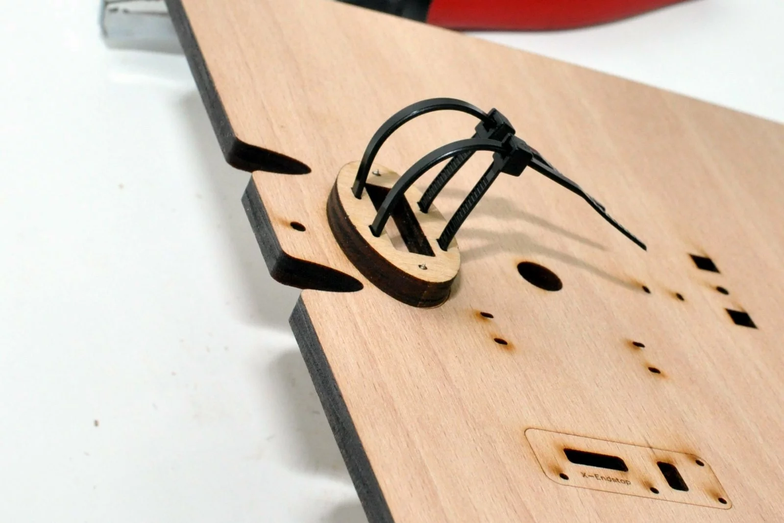
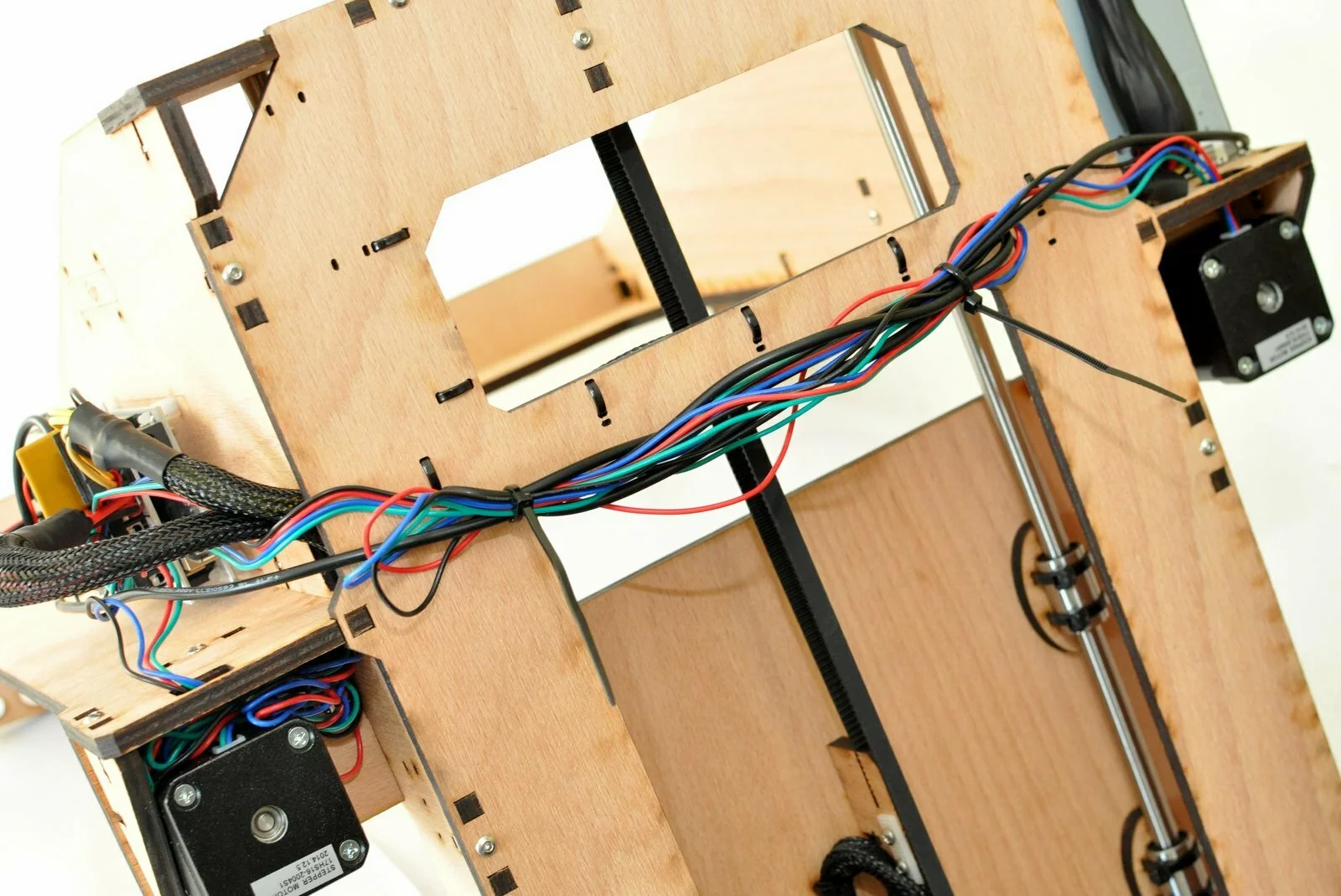
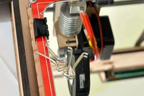
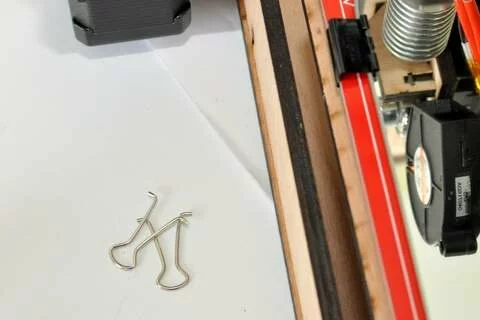
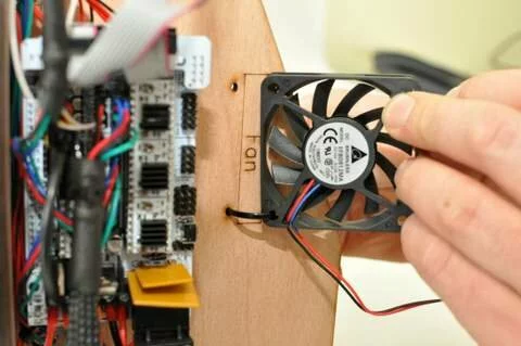
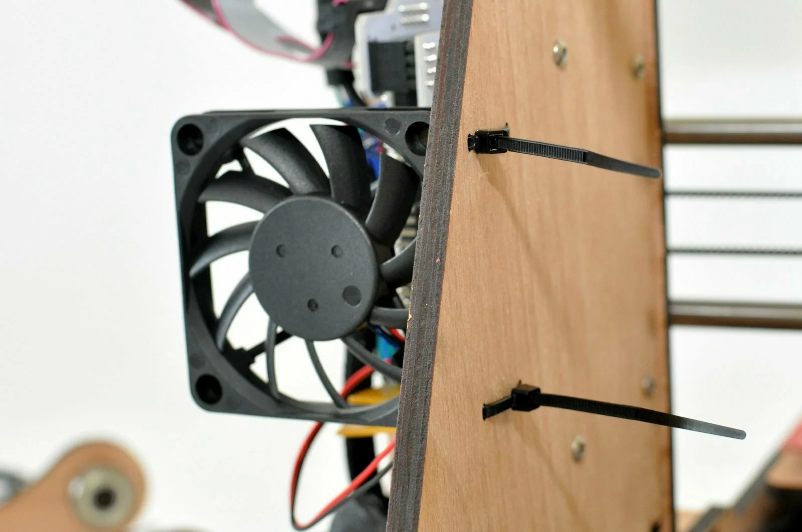
Please make sure your zipties are positioned like displayed in the image.
Step 05
Tools

Parts
Video

Steps
- Step
- Step
-
Step
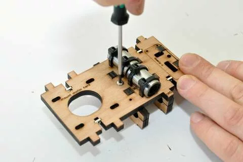
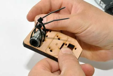
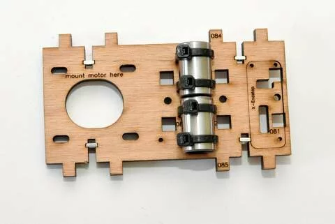
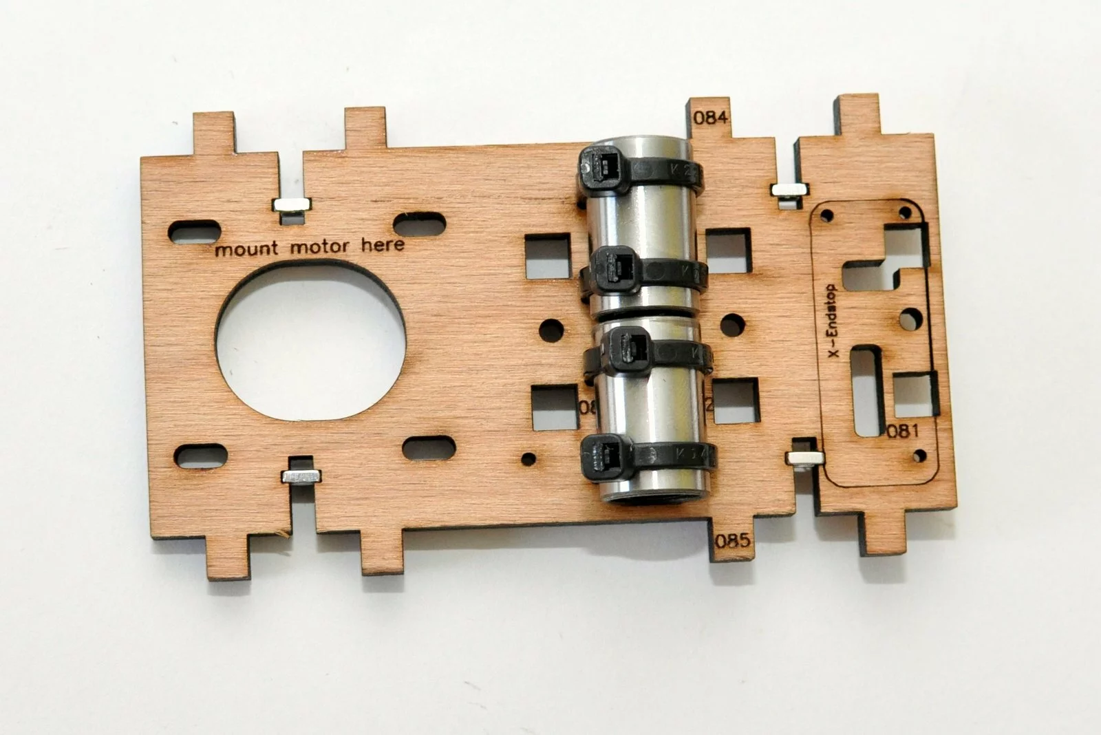
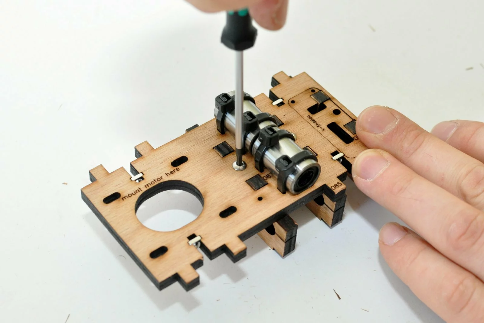
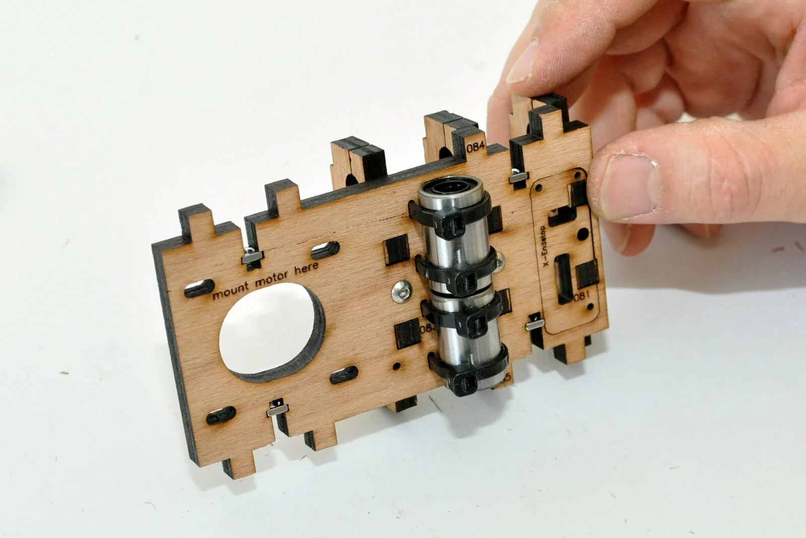
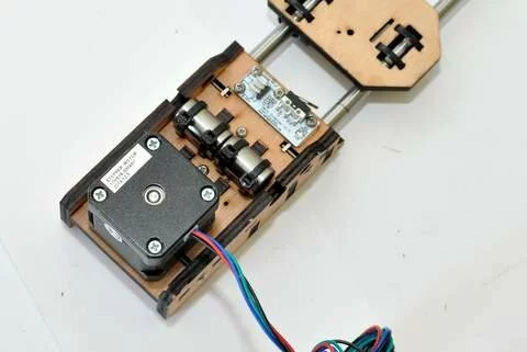
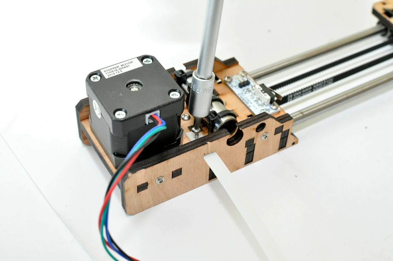
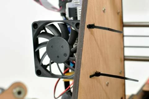
Please make sure the connnections of the zipties are positioned like shown in the picture (means the connections point to the cutout of the motor) -
Step
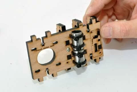
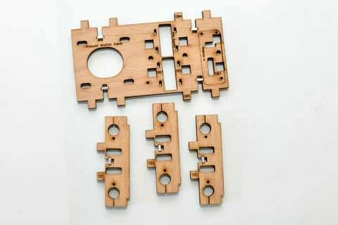
Take care! The parts 081; 082 and 083 are mounted on the backside (as the numberation won’t be hidden by the parts) - Step
- Step

- Step

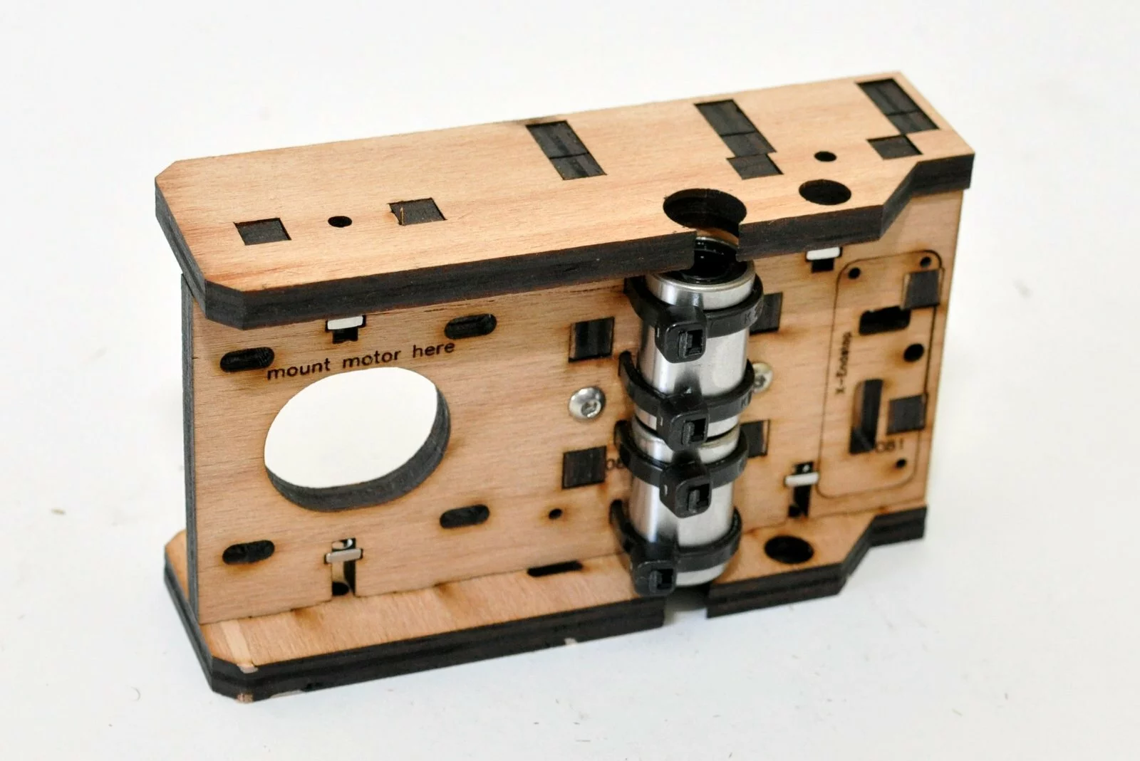
Use m3x12 screw for the last connection

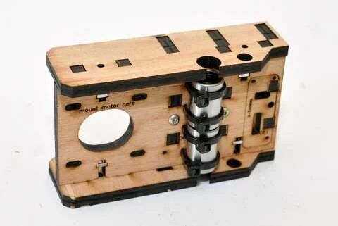
Result
Use m3x16 screws to connect the top & bottom of this assembly
Step 06
Tools

Parts

Video

Steps
- Step
- Step
- Step
-
Step
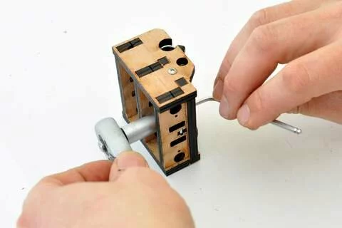
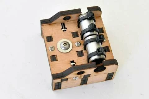
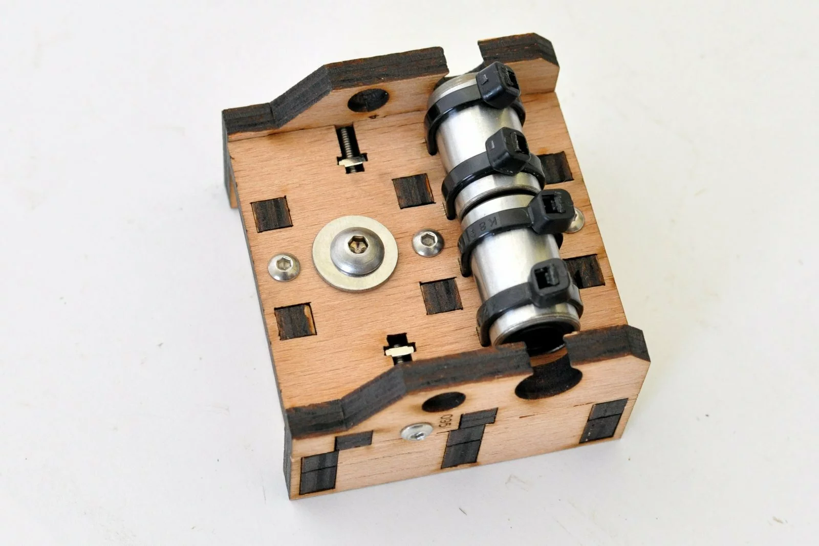
Please make sure that the connections of the zipties are positioned on the side of the linear bearings (like shown in the image above) -
Step


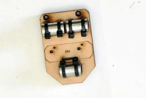
Result
Step 07
Tools
Parts
Video

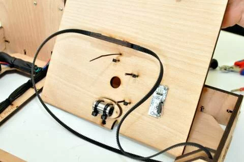
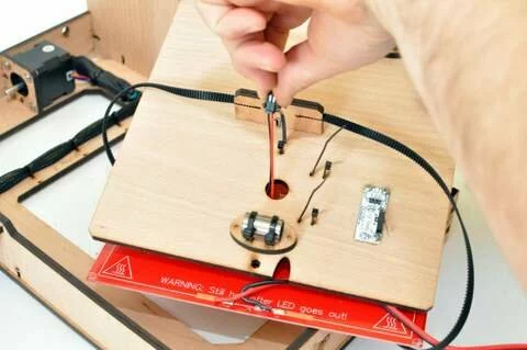
Steps
- Step
-
Step
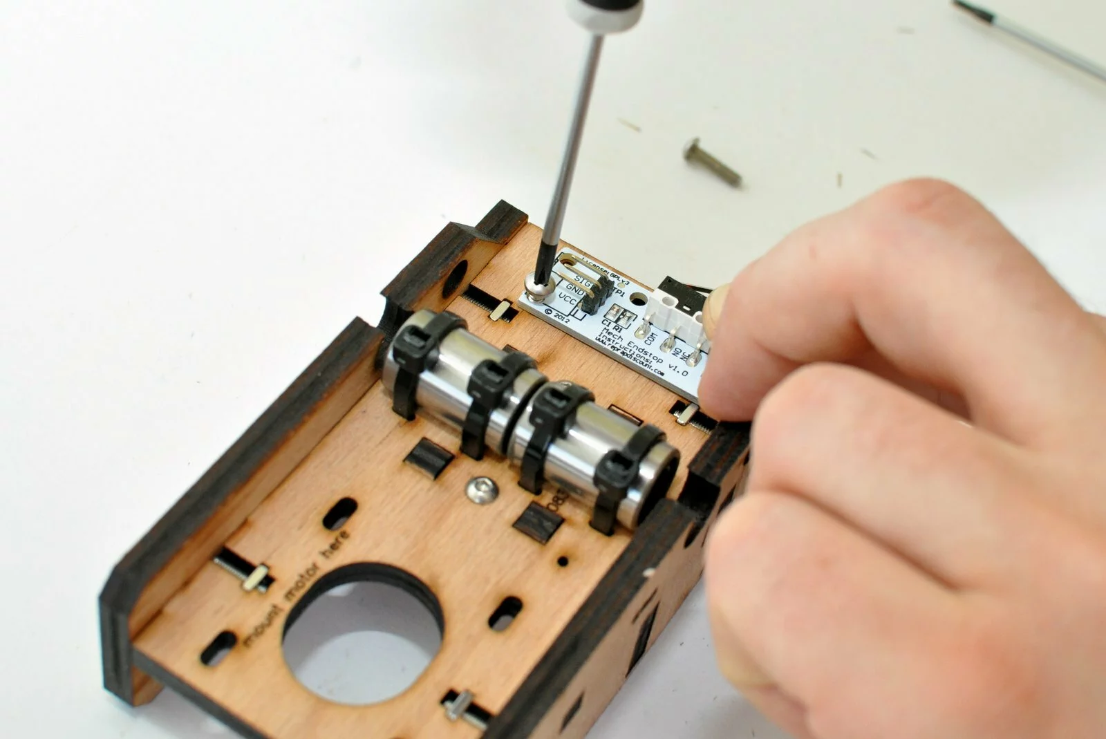
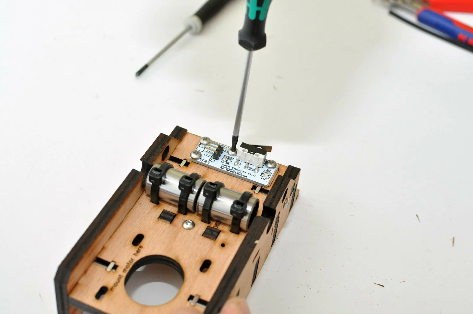
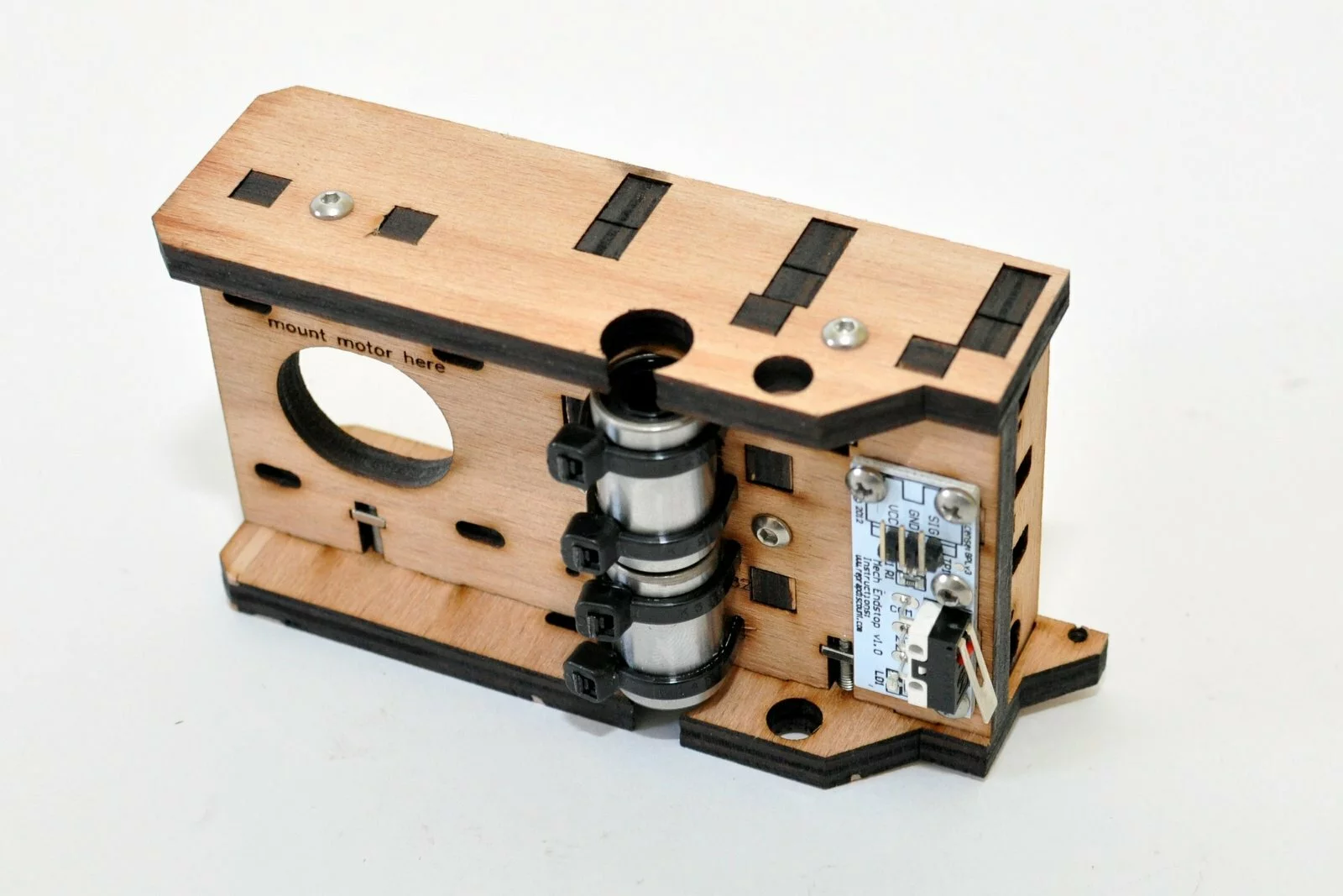
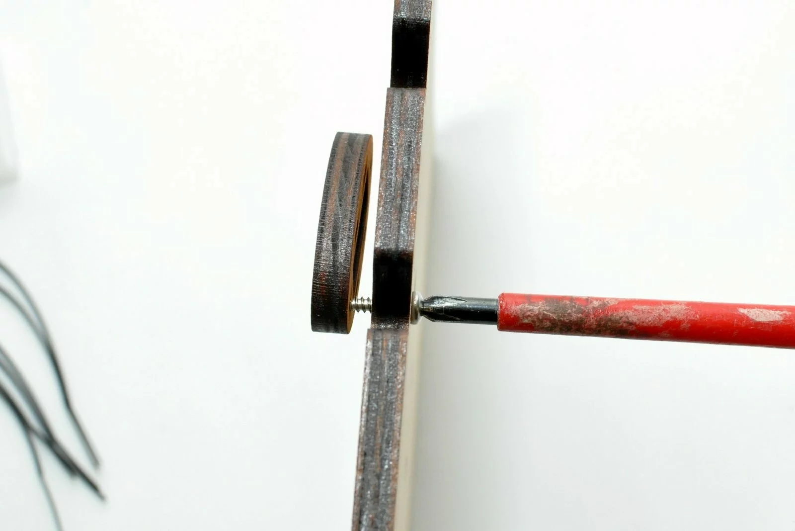
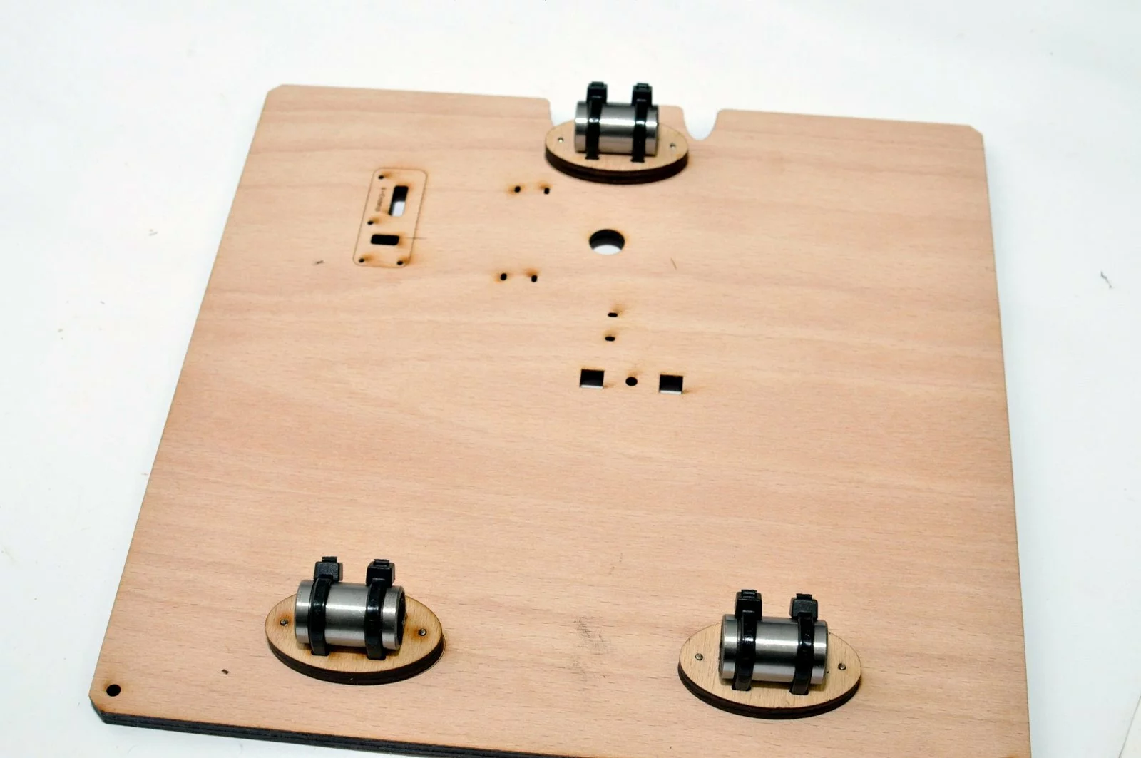
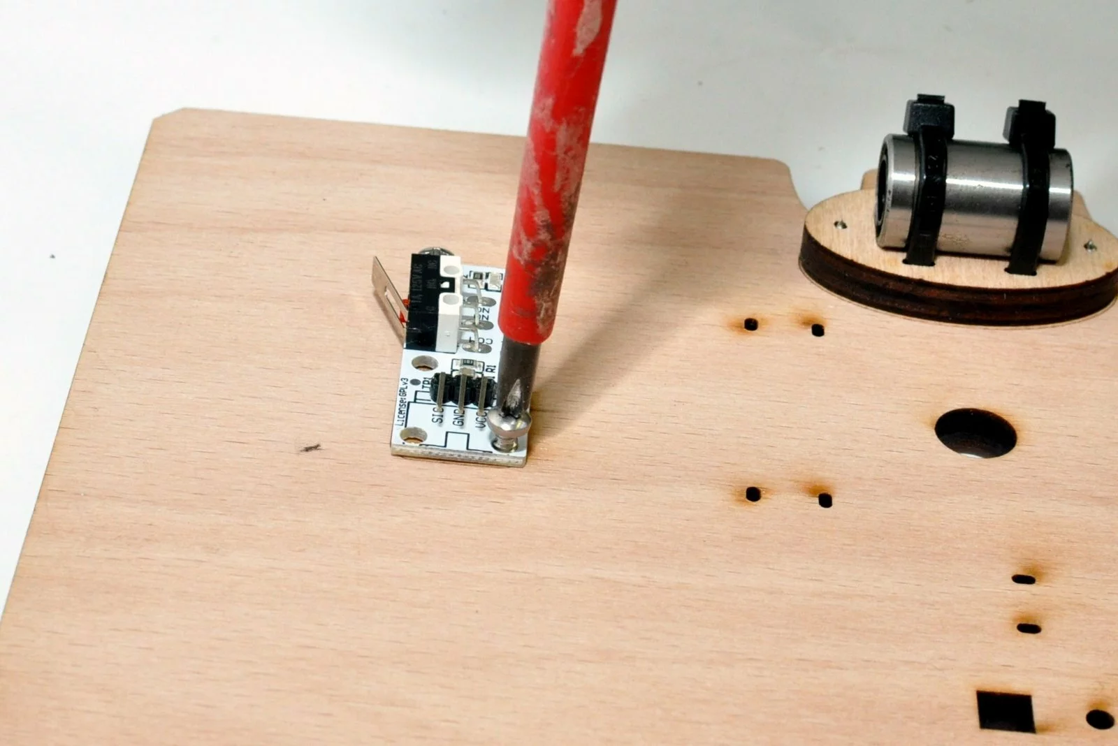
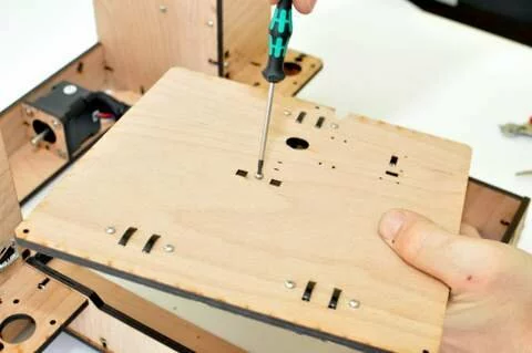
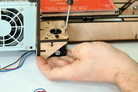
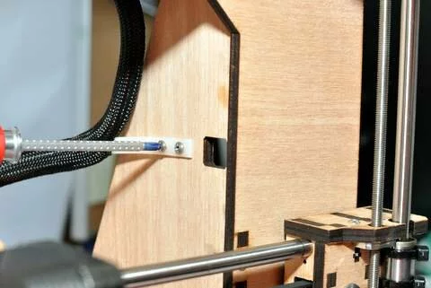
Fix the wooden spacers on the bottom of the table ( the side that does contain the placemarker for the endstop) use 2,9×13 wood screws -
Step
- Step

- Step
- Step


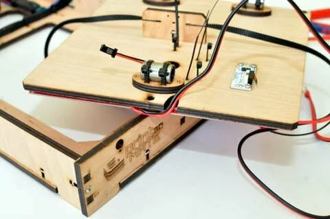
Result

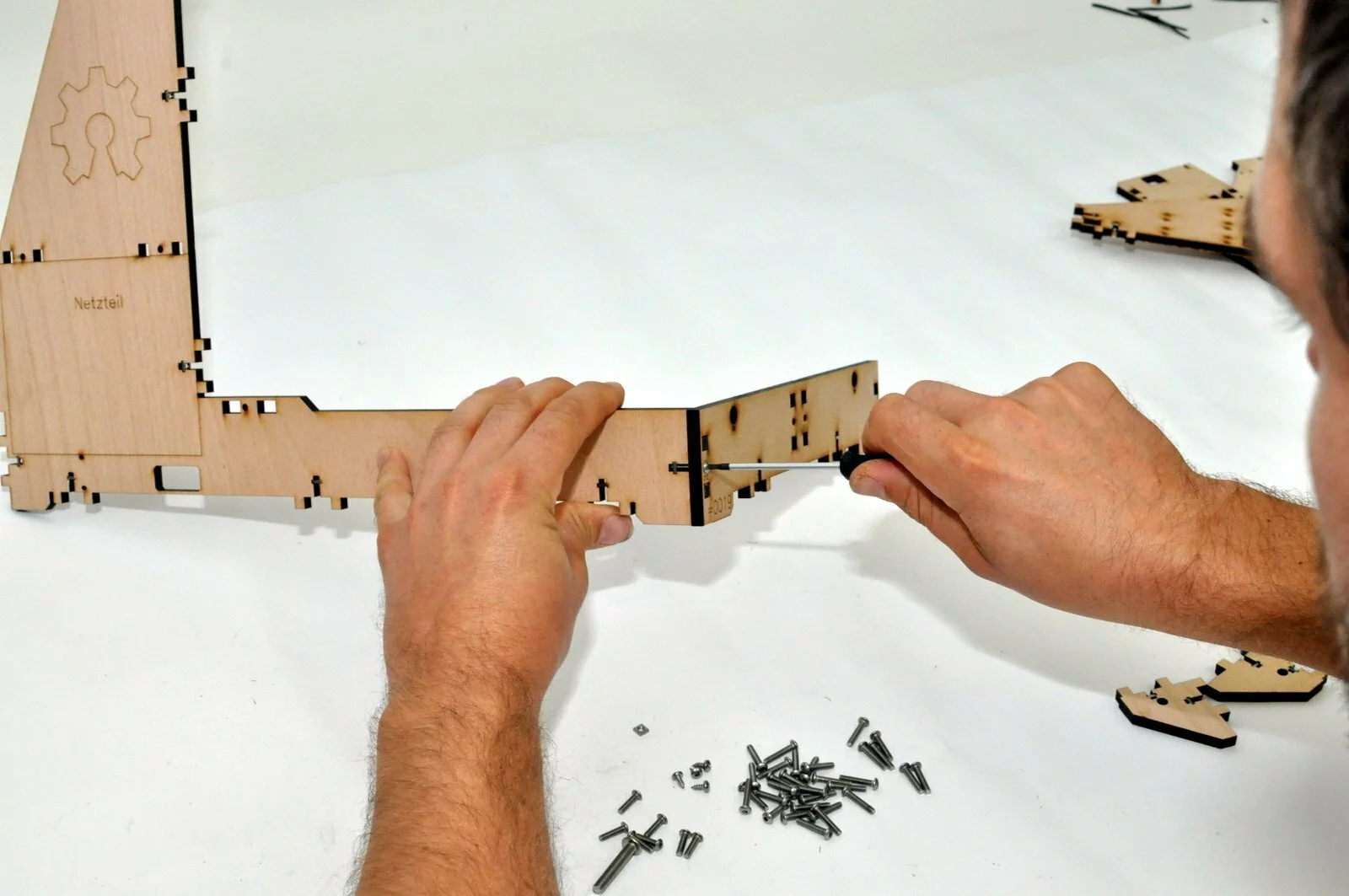
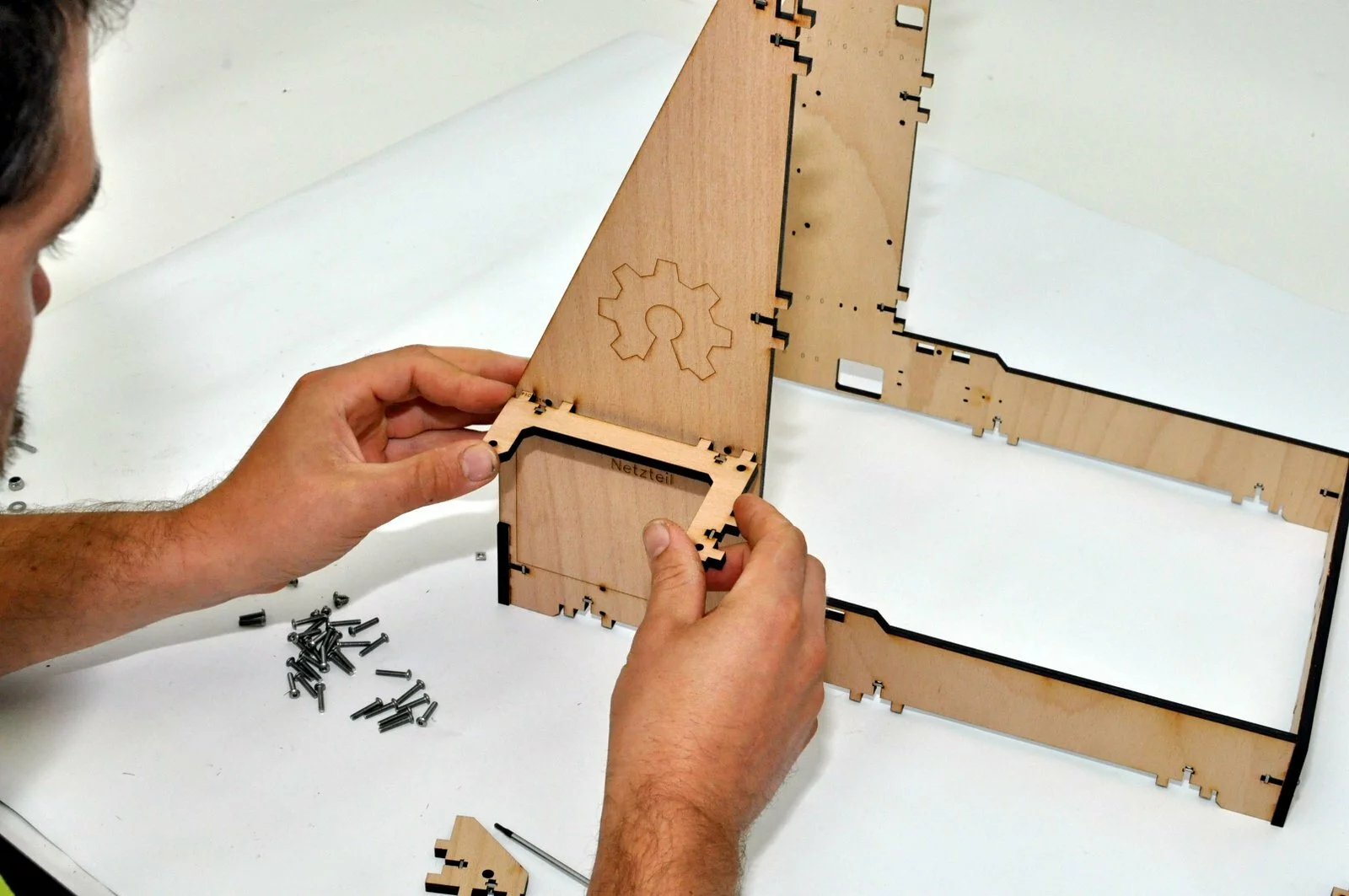
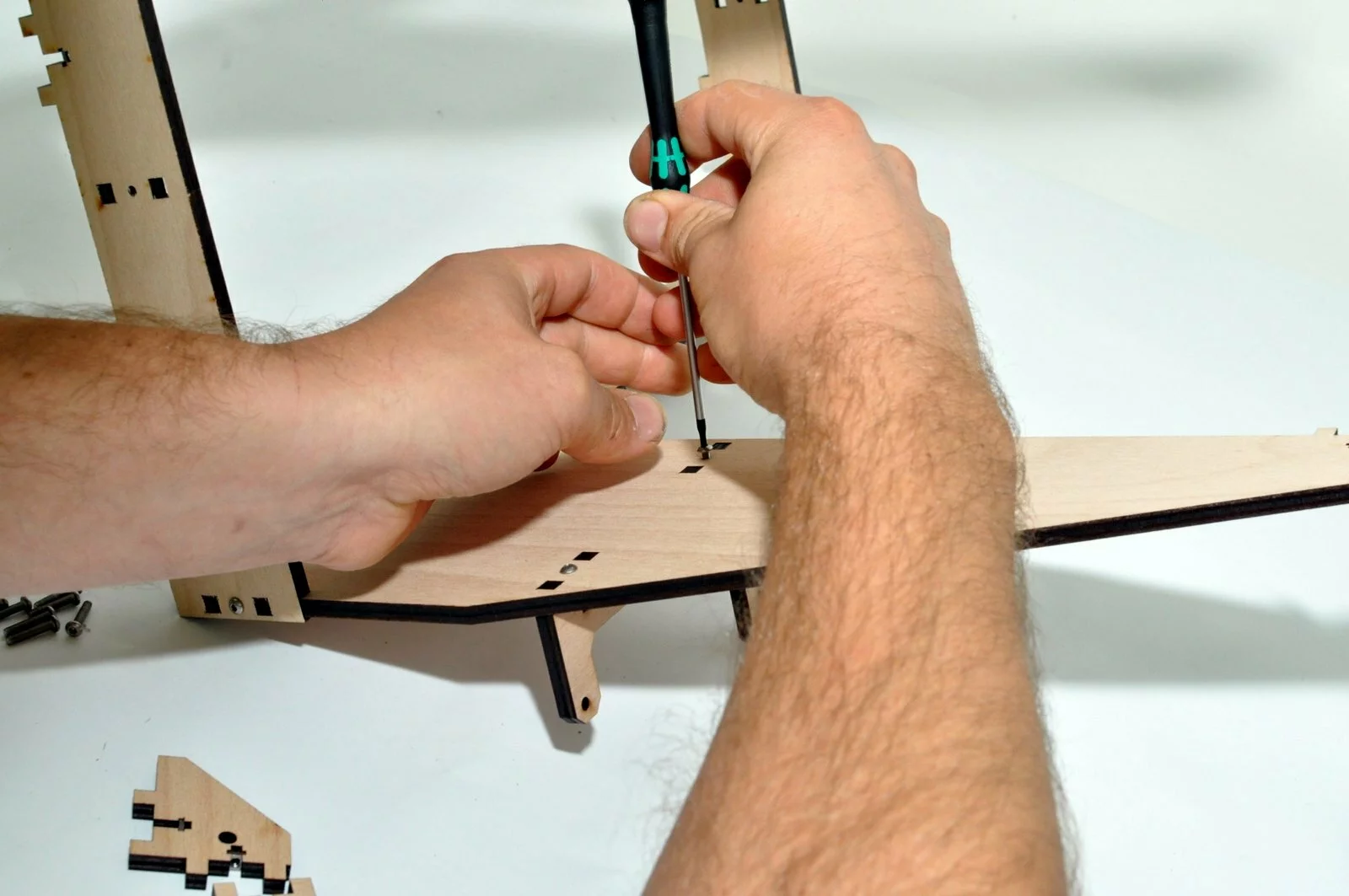
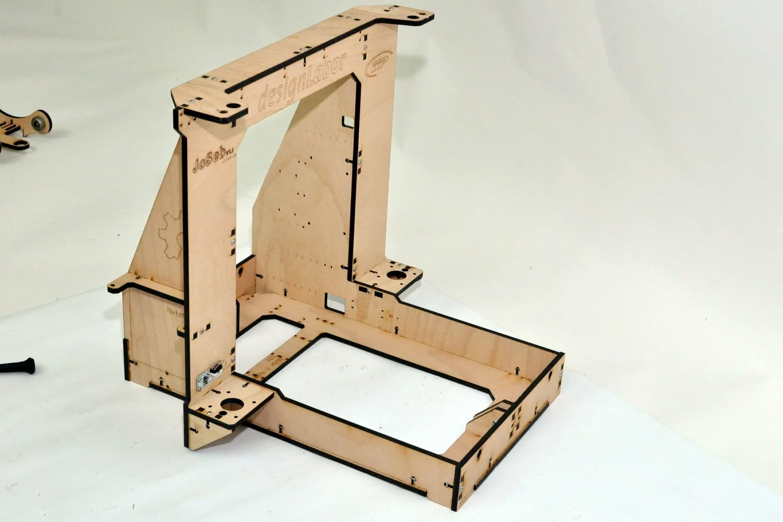
Step 08
Tools
Parts

Video

Steps
- Step

- Step
- Step
- Step
- Step
- Step
- Step
- Step
-
Step
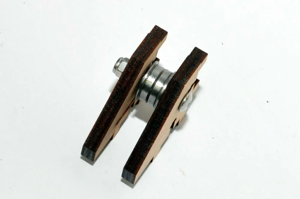
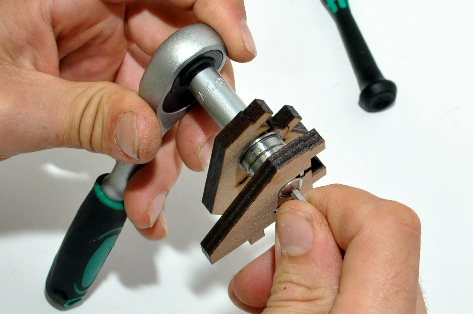
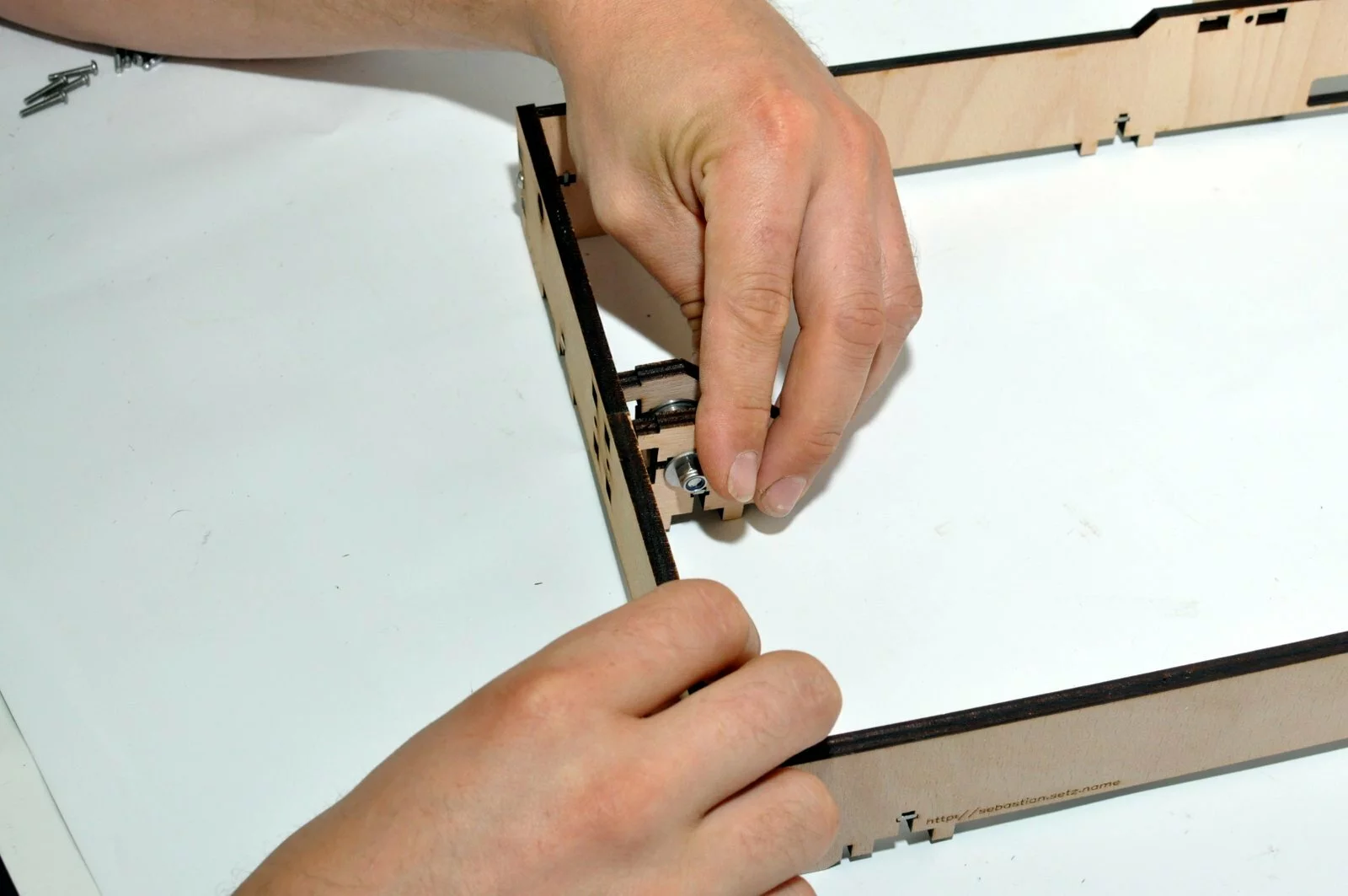
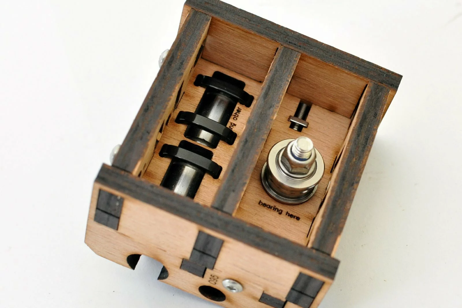
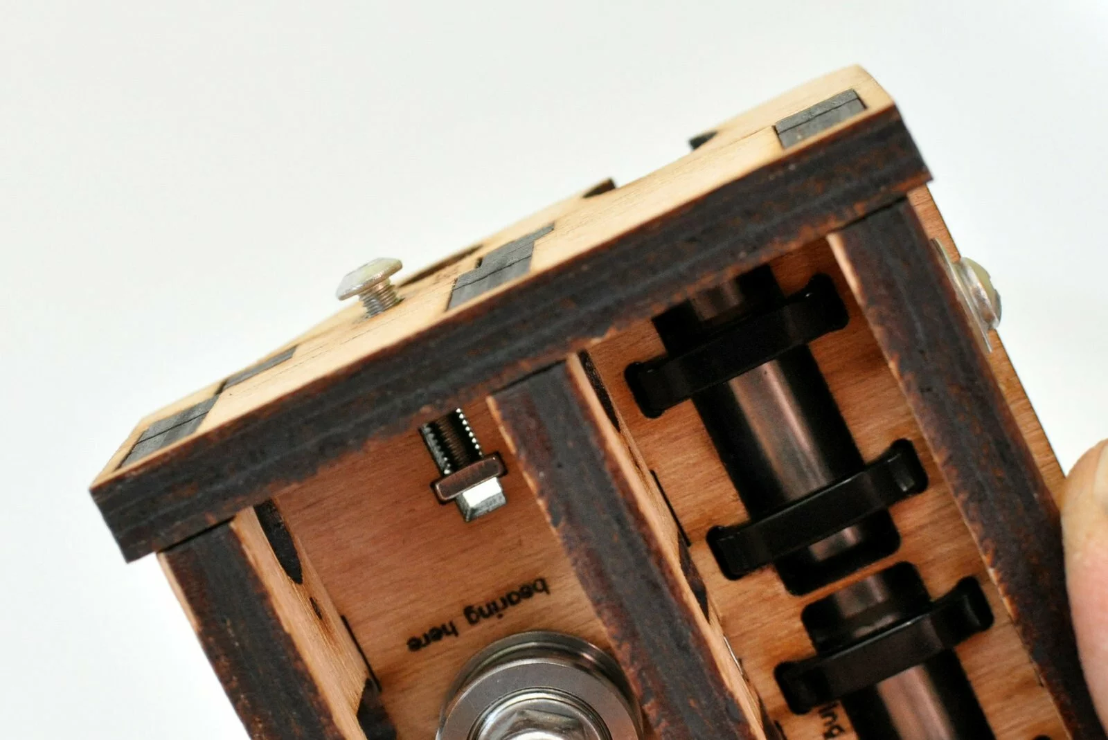
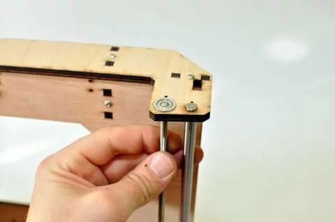
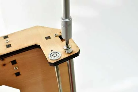
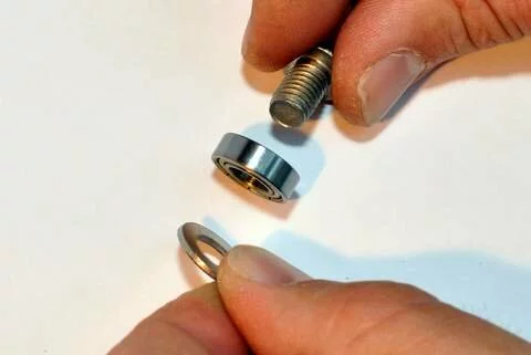
Place the small washers next to the bearing. The big washer is placed on the outside under the nut. -
Step
- Step

- Step

- Step
- Step
- Step

- Step

- Step
- Step
- Step
- Step
- Step

- Step
- Step
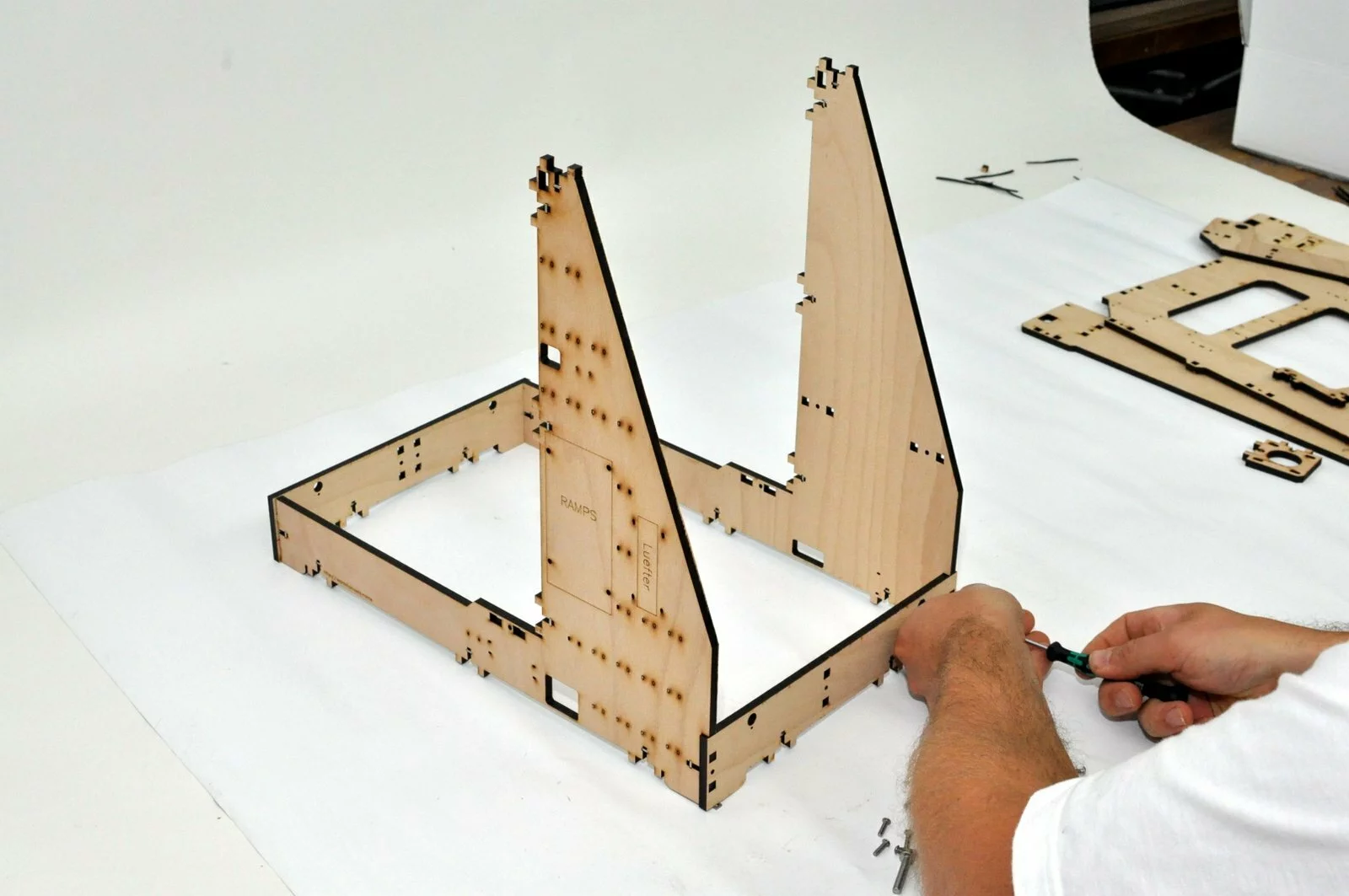


Result
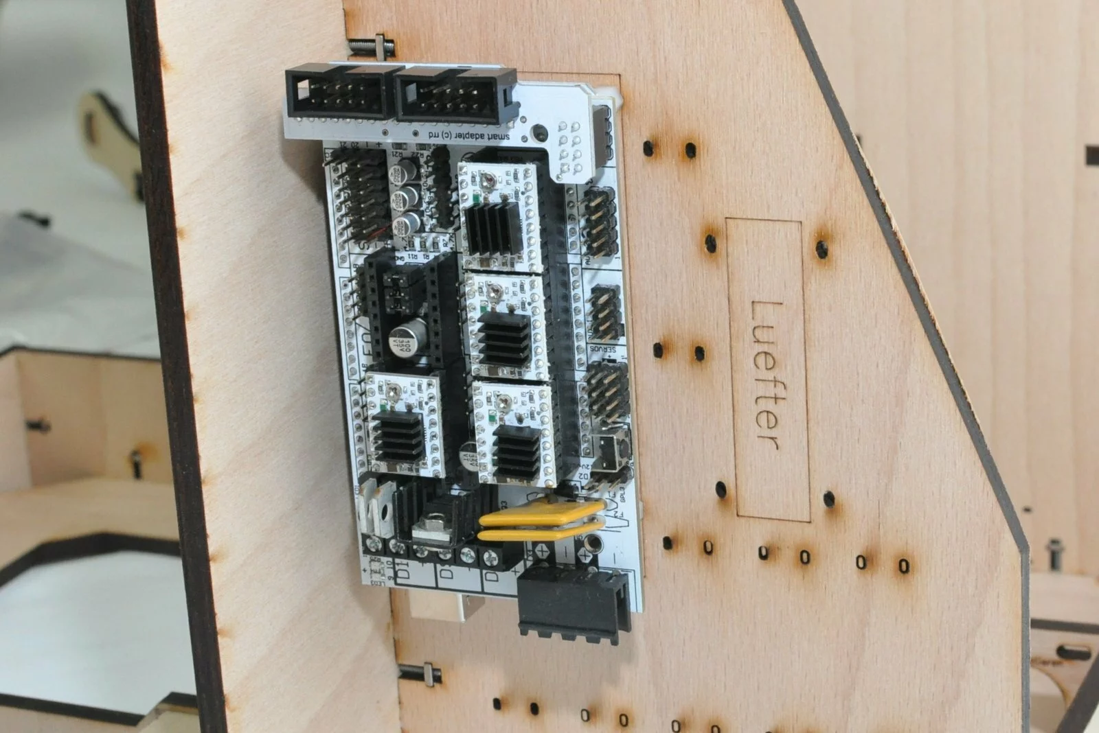
Step 09
Tools
Parts
Video

Steps
- Step
- Step

- Step
- Step
- Step

- Step
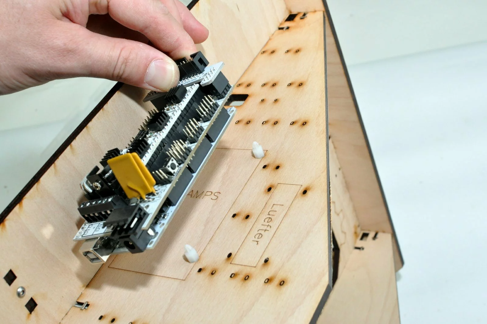
Result
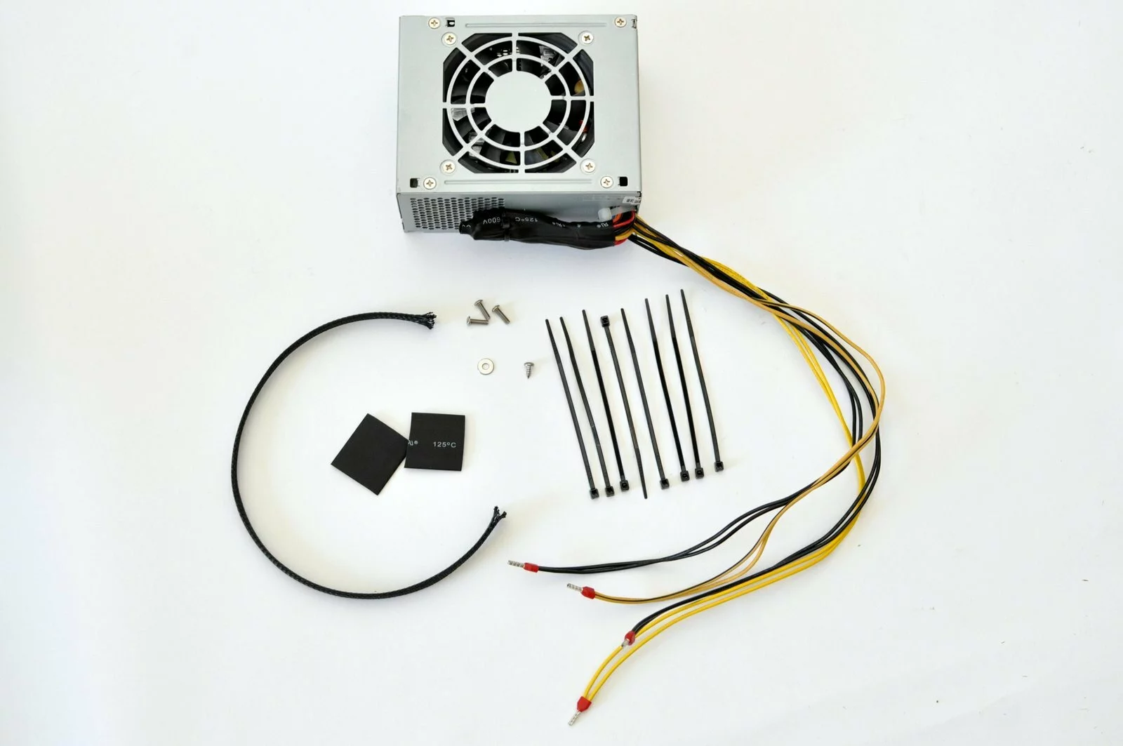
Step 10
Tools
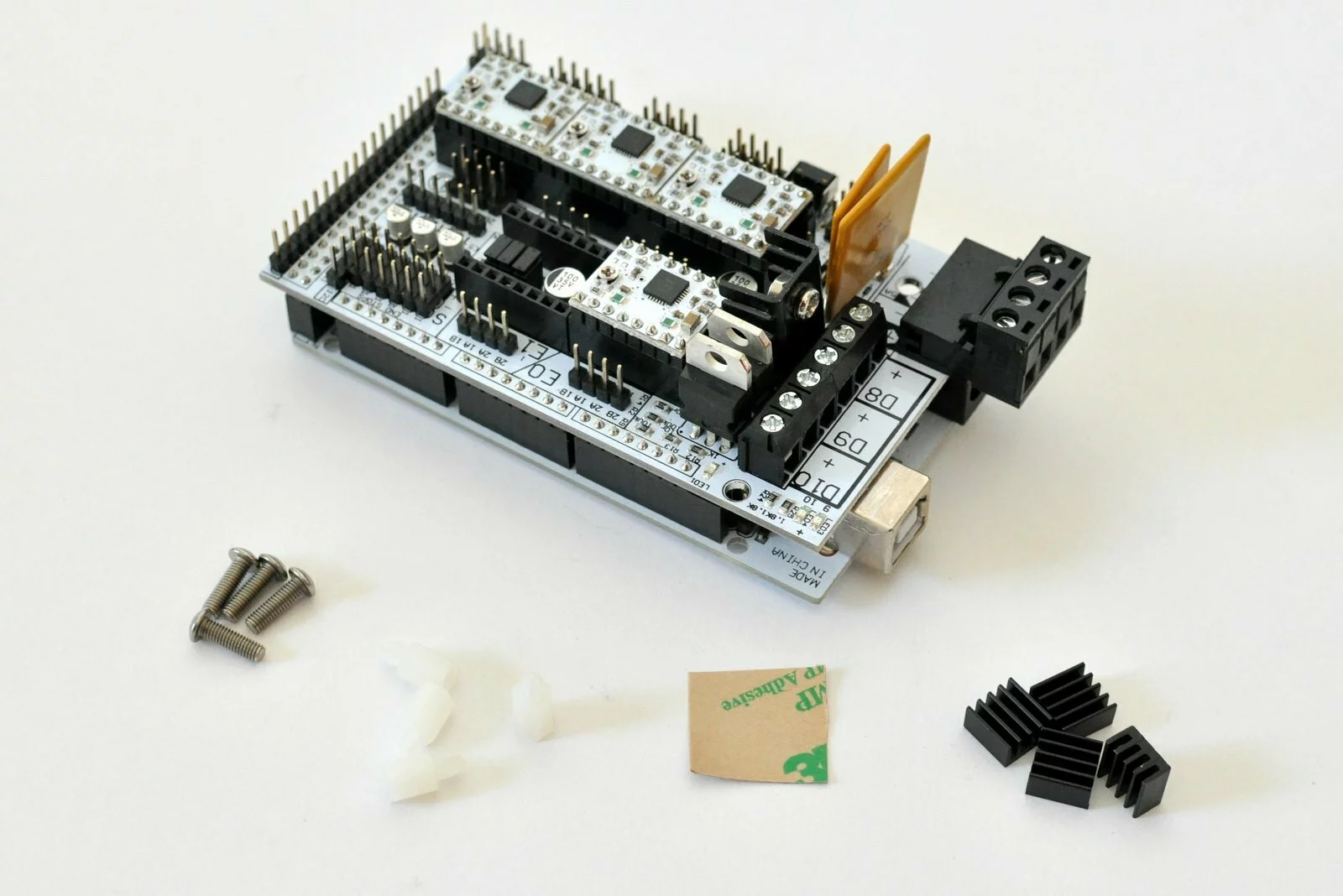
Parts
Video

Steps
- Step
- Step
- Step
- Step
- Step

- Step
- Step
- Step

- Step
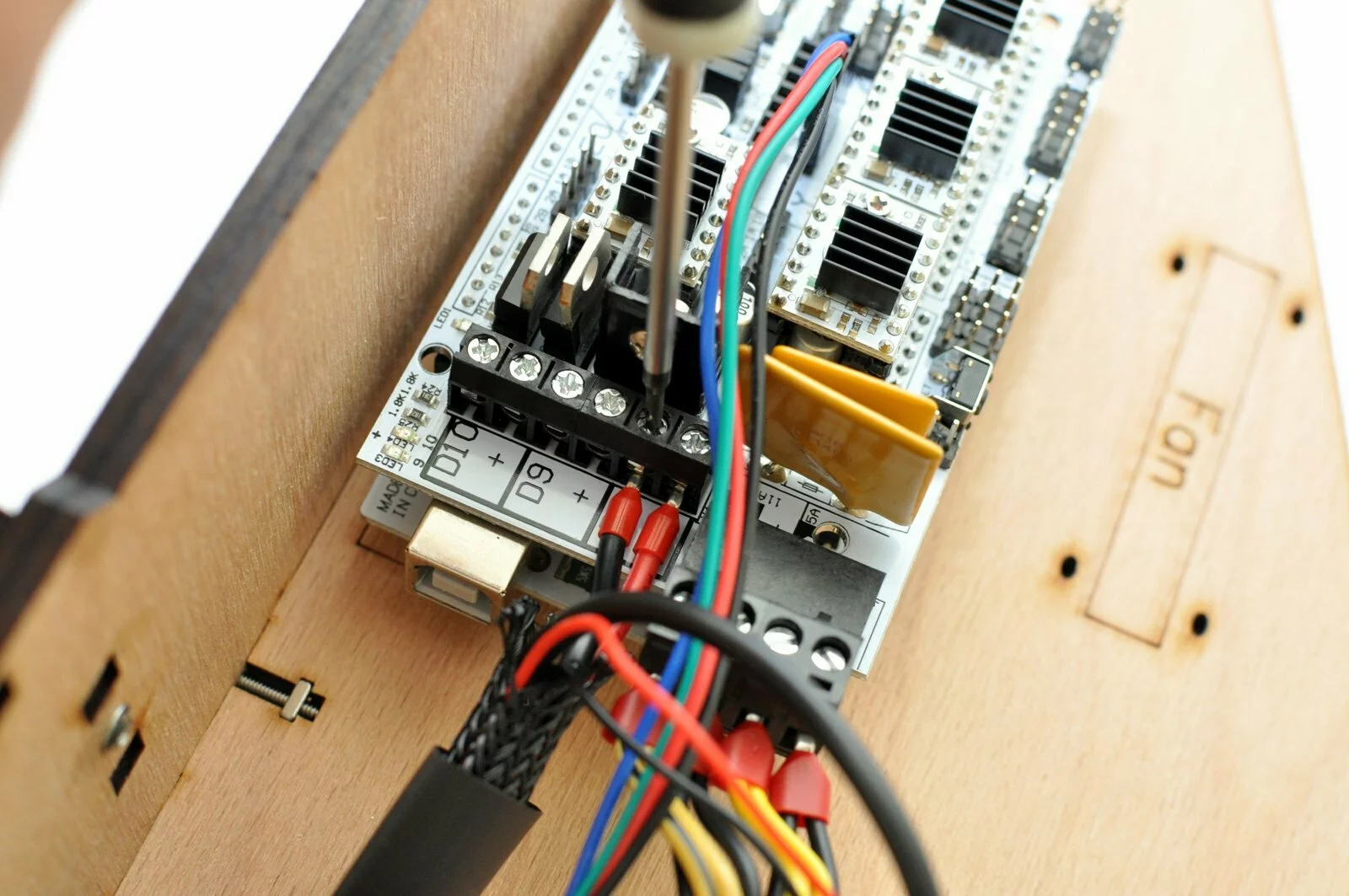
- Step

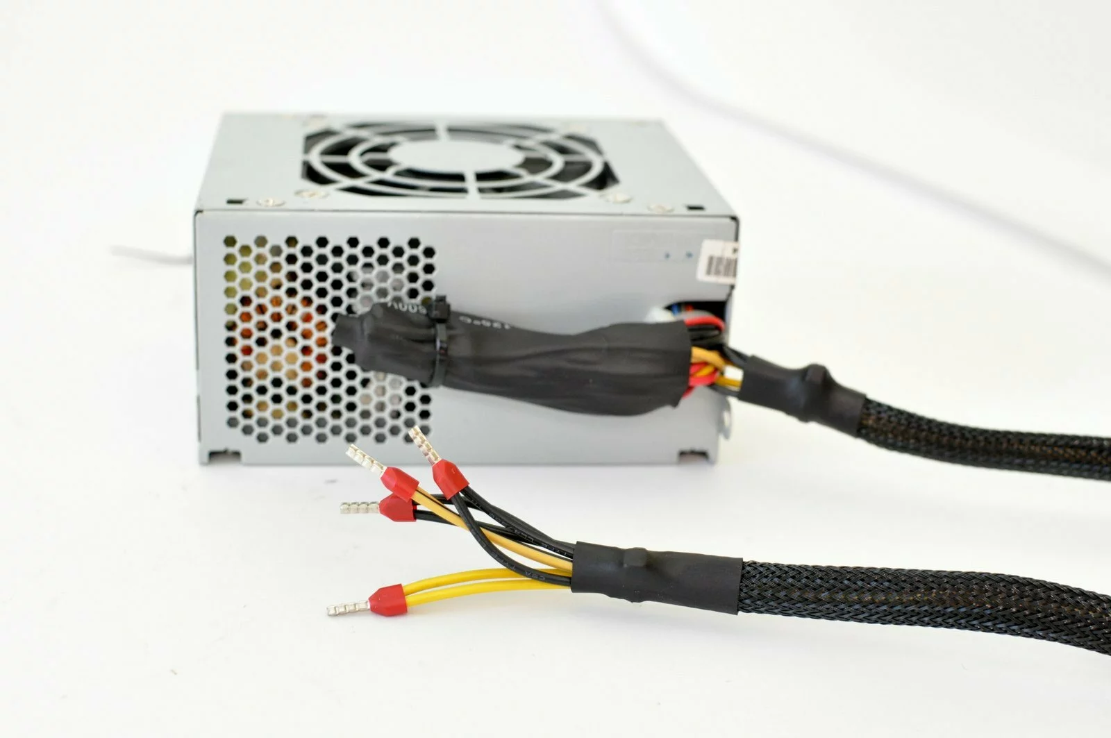


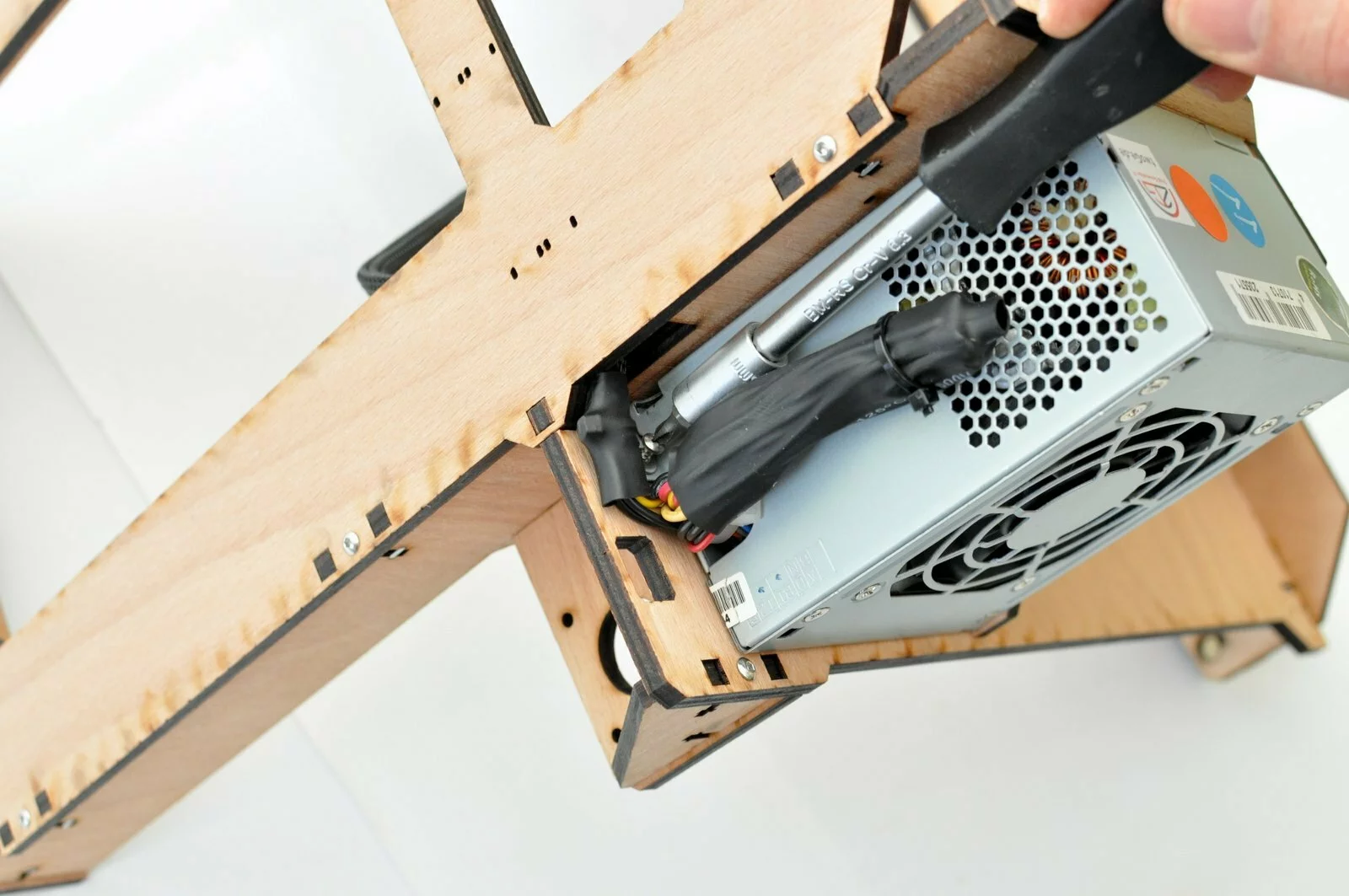


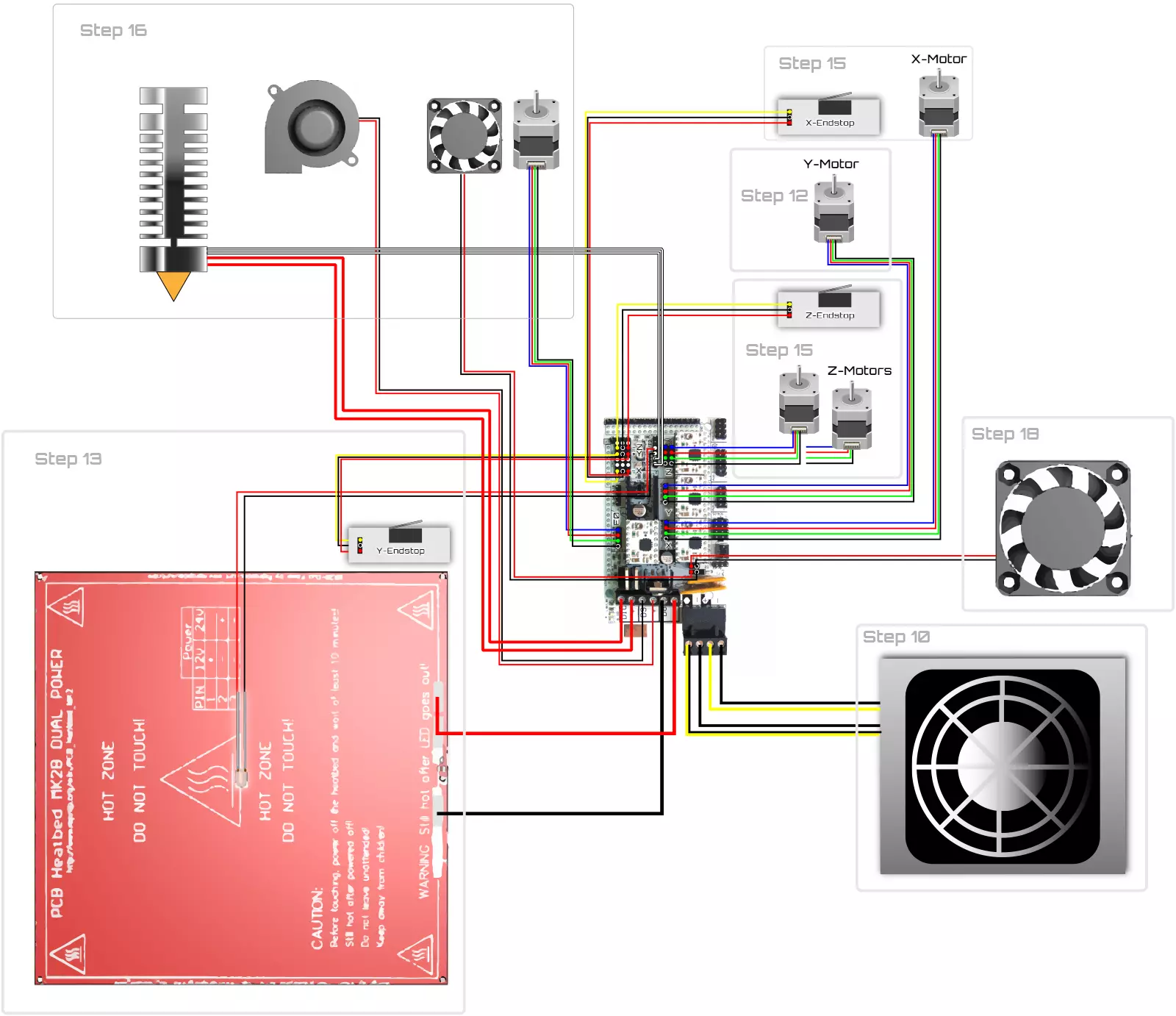
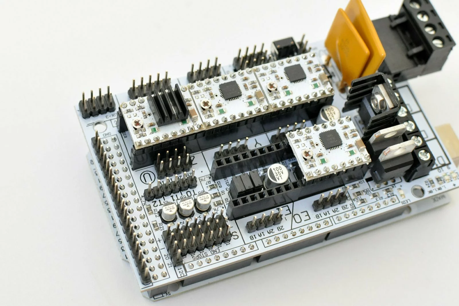
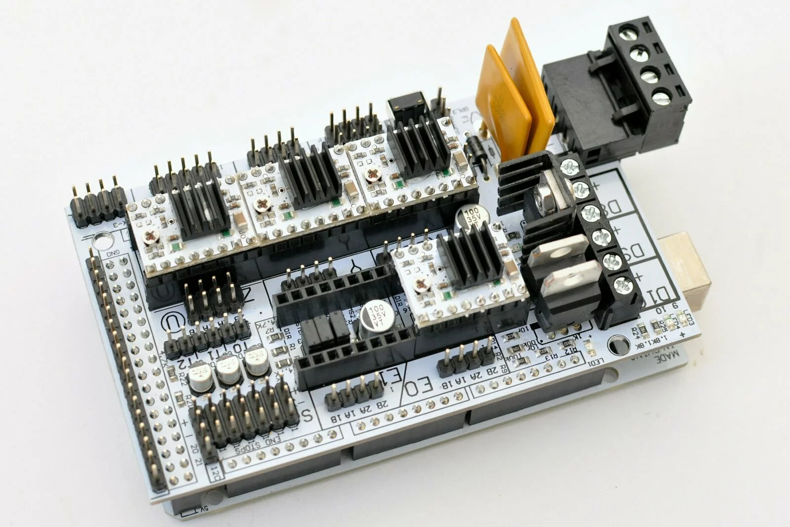
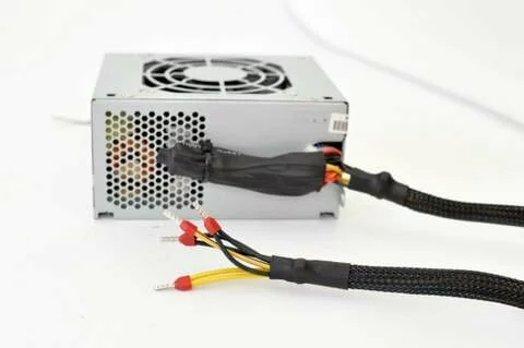
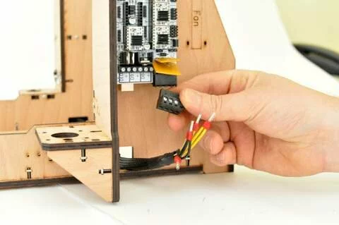
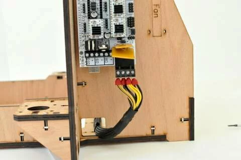
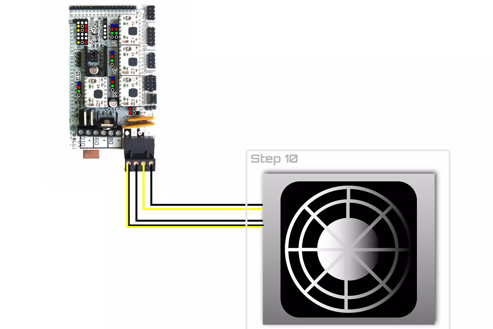
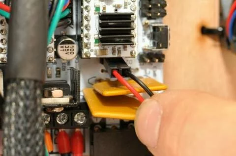
The power supply provides two differents currents. The input for the heated bed requieres the higher current. Connect the wires like shown in the image above. The yellow black cable is the plus input for the 11A connection of the RAMPS board
Wiring
Result
Step 11
Tools
Parts
Video

Steps
- Step
- Step

- Step
- Step

- Step
- Step
- Step
- Step
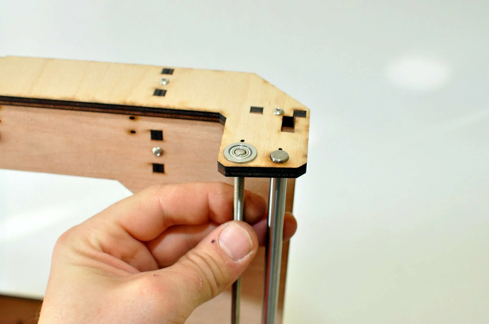
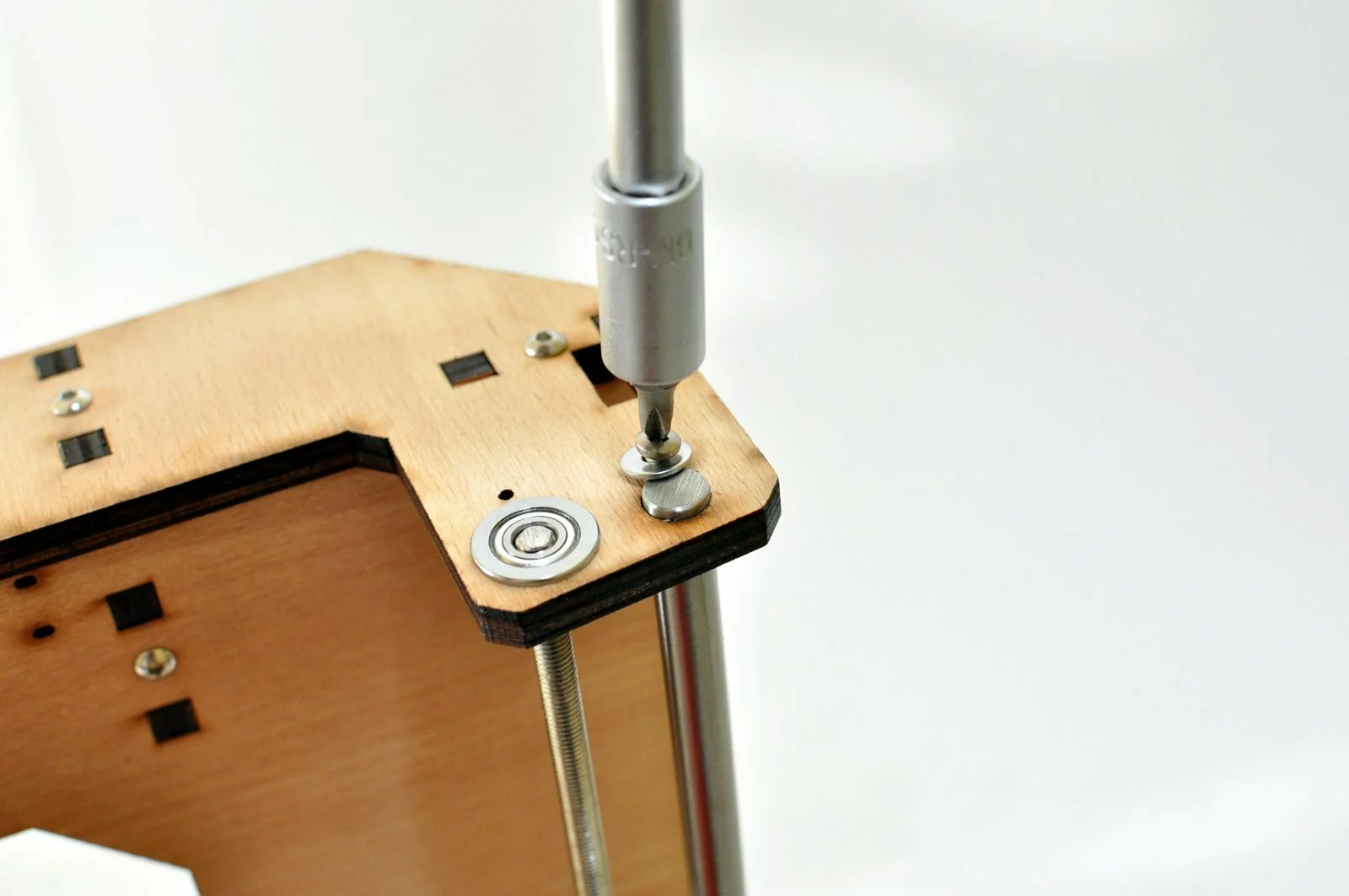
-
Step
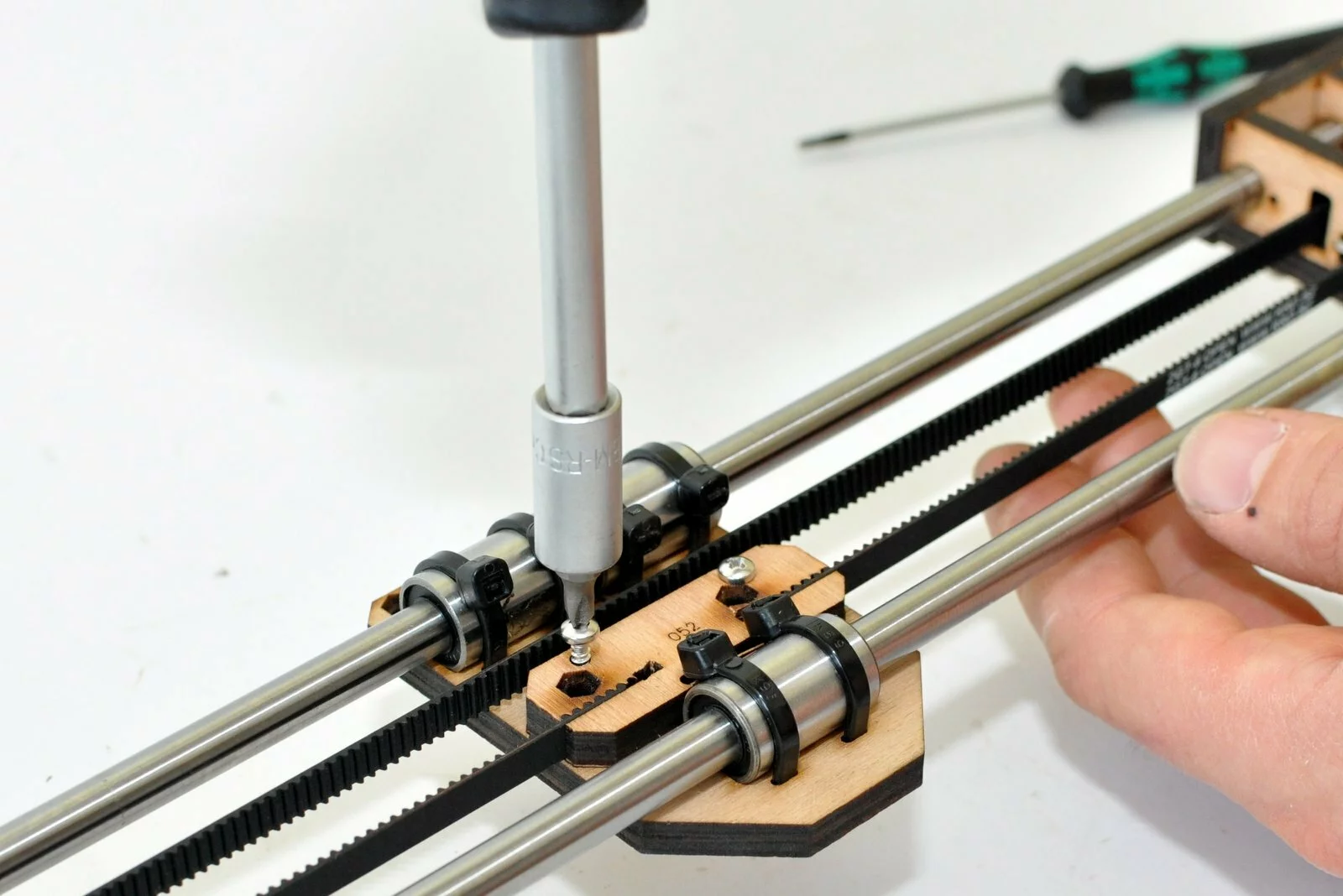
Use m5x25 screw – the small washers are placed next to the bearing – the big washer is mounted underneath the screw head. -
Step

- Step
- Step
- Step
- Step
- Step
- Step
- Step
- Step
- Step
- Step
- Step

- Step

- Step
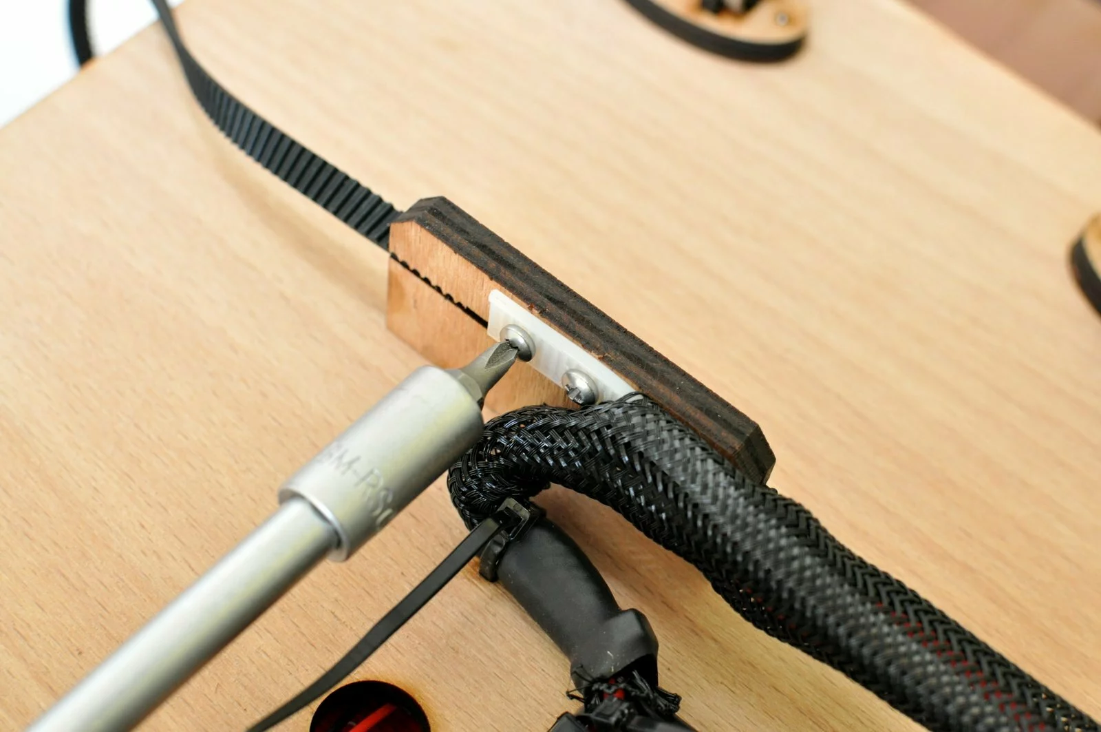
-
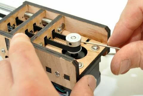
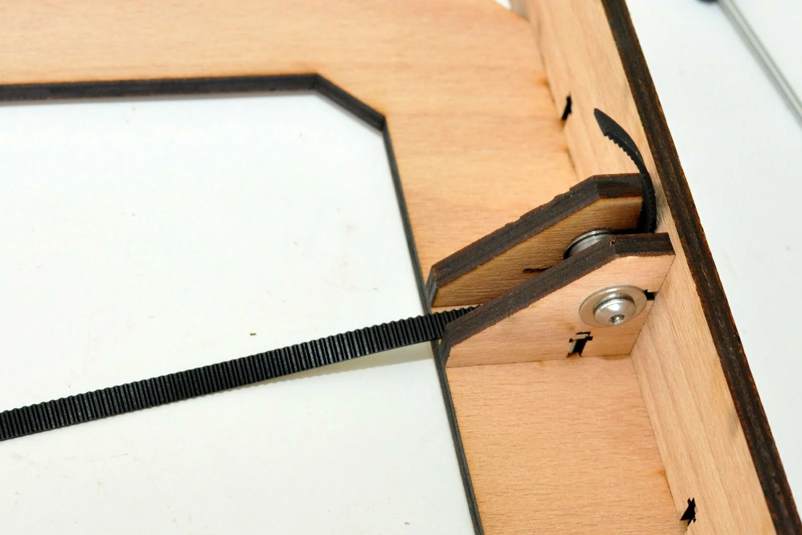
Step
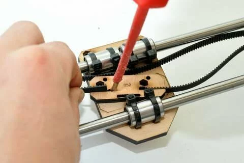
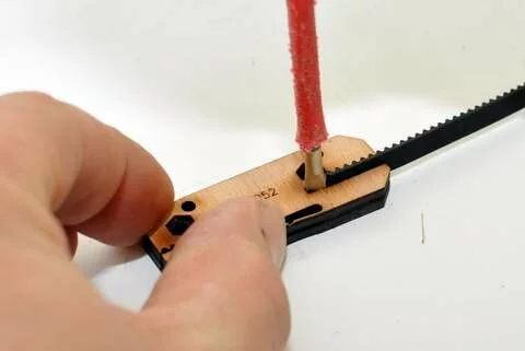
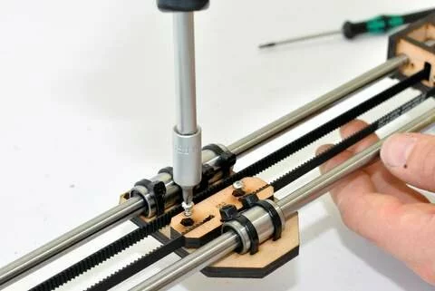
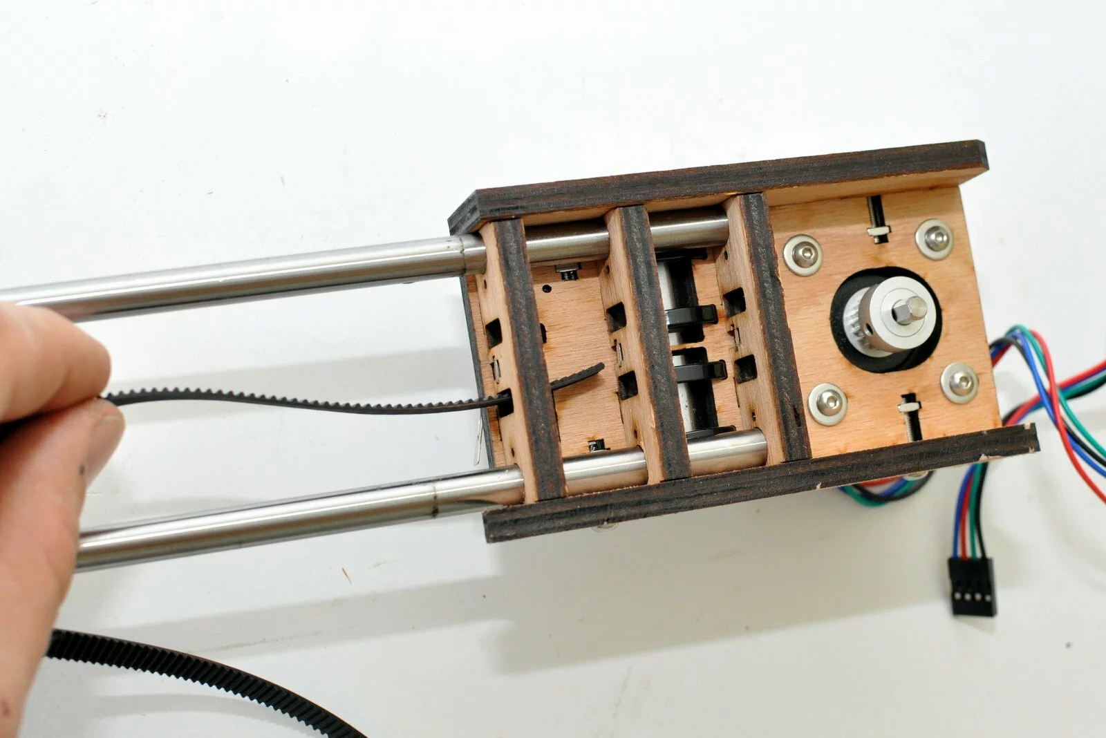
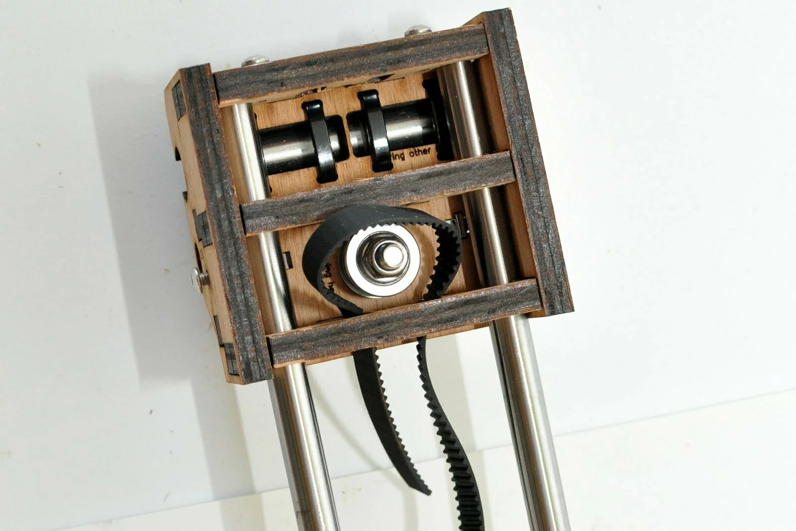
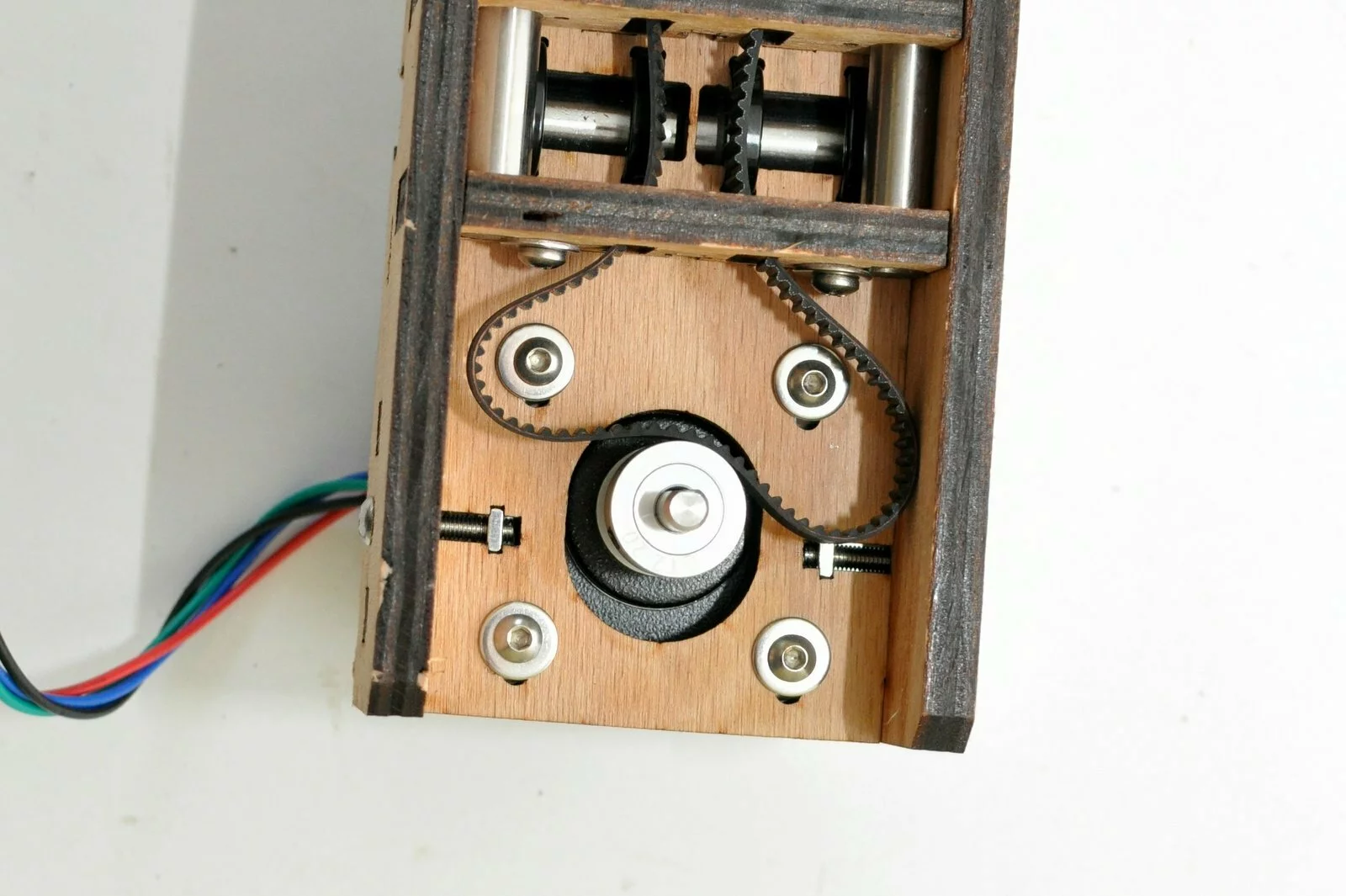
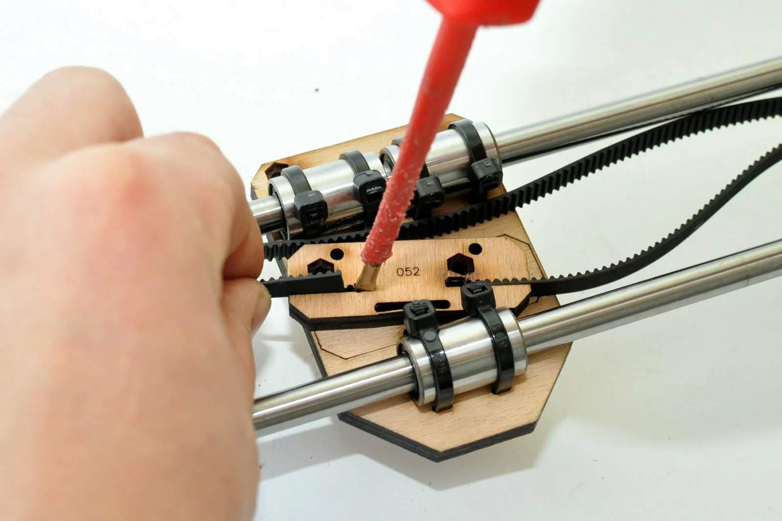
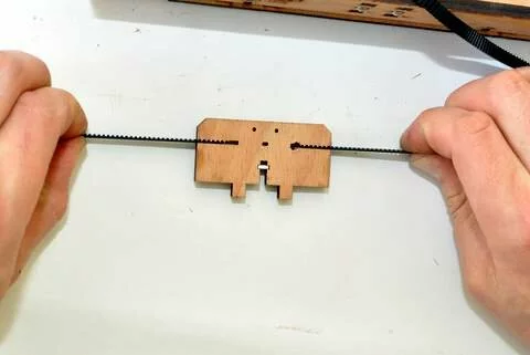
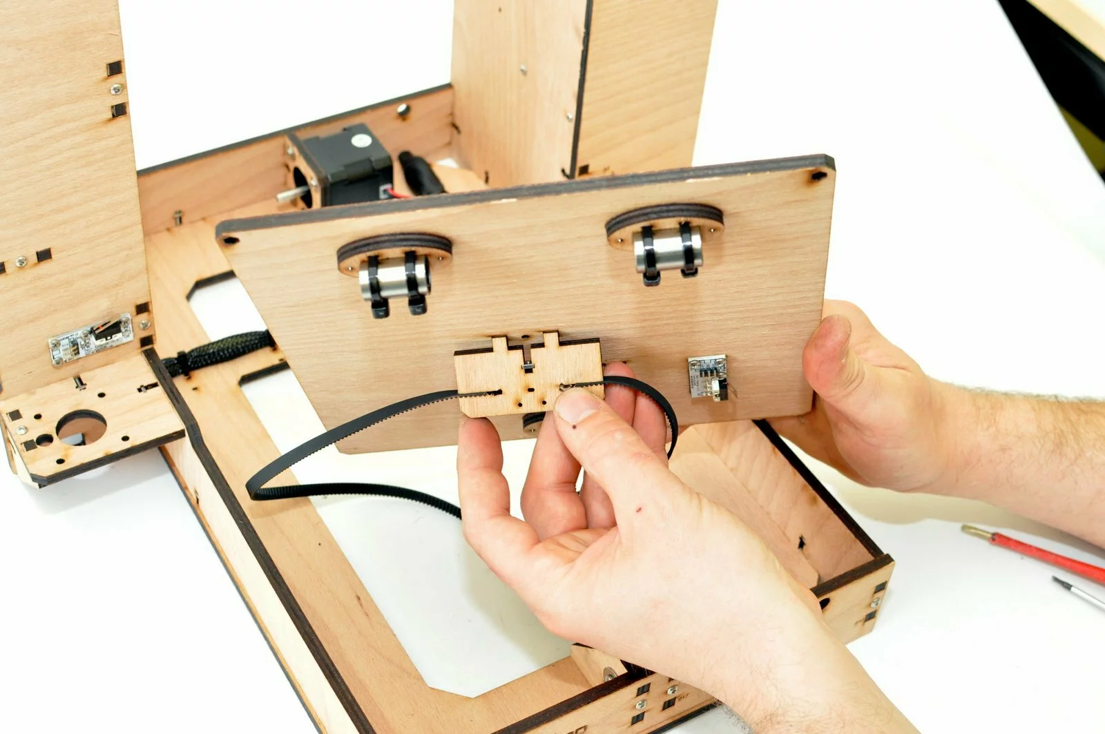
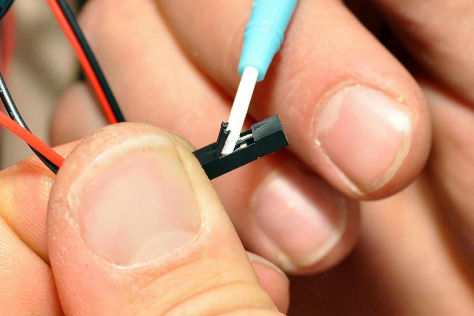
Insert the belt according to the image. Note that it is easier to insert the belt into the belt connector from the top side (the side that contains the numeration). Use a screwdriver to spread the belt connector this facilitates the inserting of the belt. -
Step
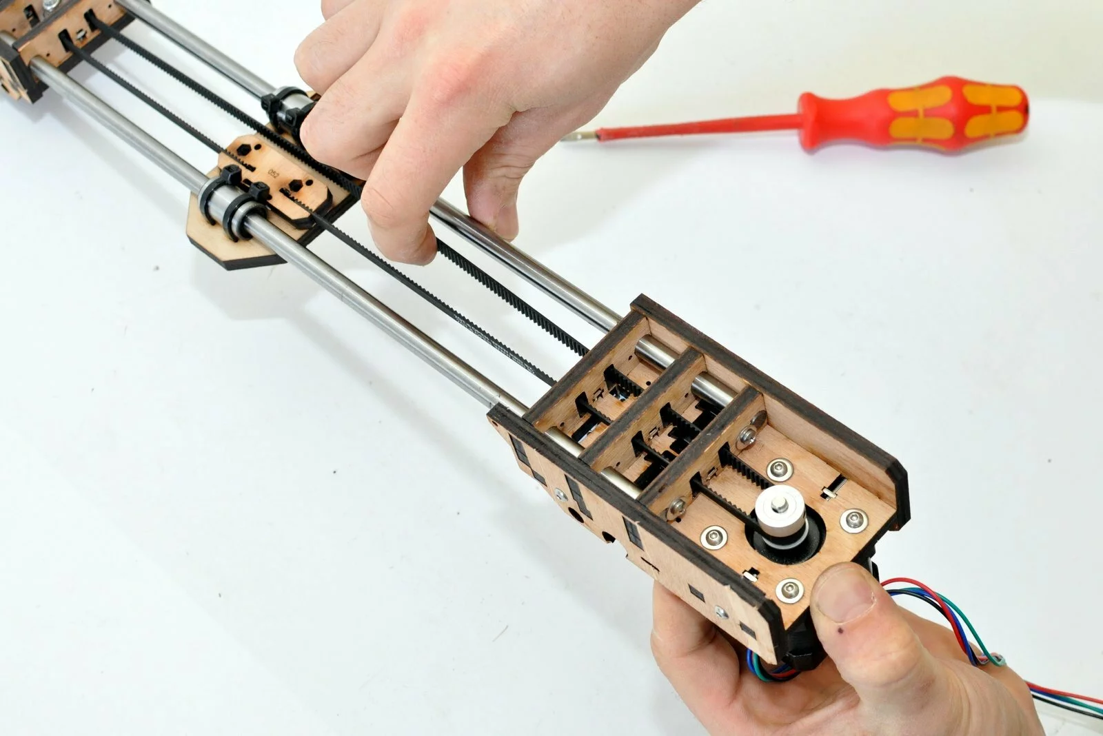
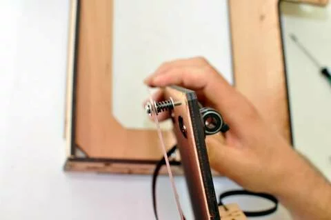
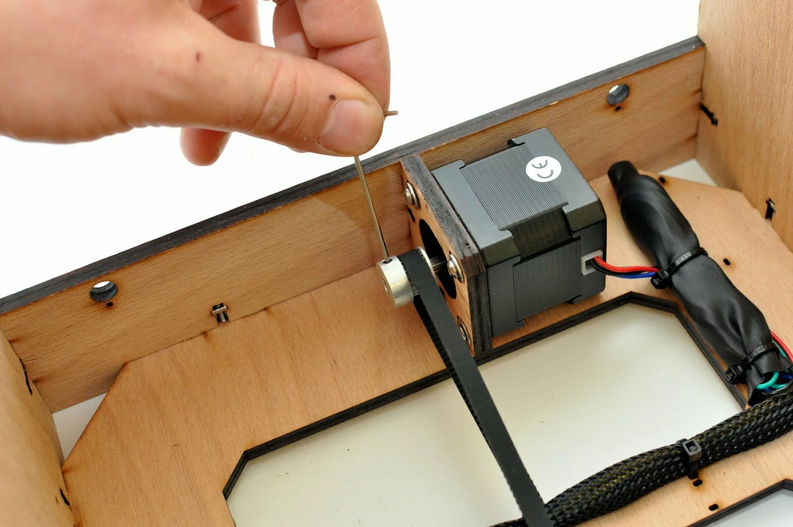
-
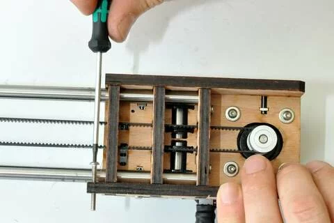
Step
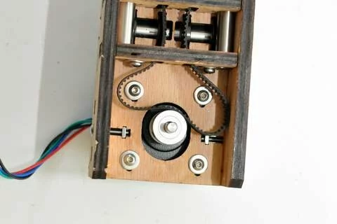
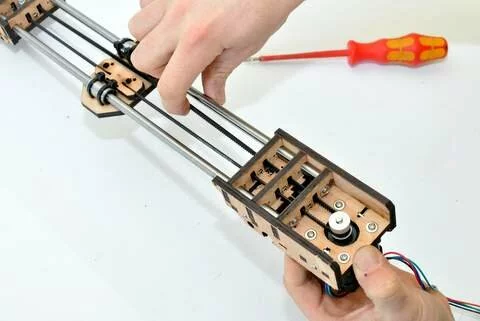
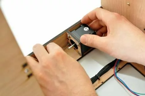
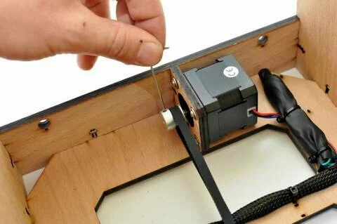
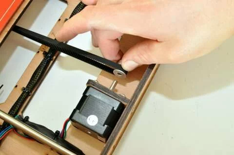
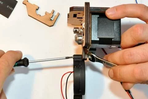
Tension the belt by pulling the motor like shown in the image. It is necessary to apply some force when tensioning the belt. -
Step
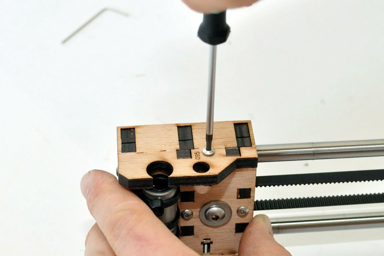
-
Step
Use 2,9×13 wood screws -
Step

- Step

- Step
- Step
- Step
- Step
- Step
- Step
- Step
- Step


Result
Step 12
Tools
Parts
Video

Steps
- Step

- Step
- Step
- Step

- Step
- Step

- Step
- Step
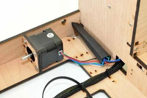
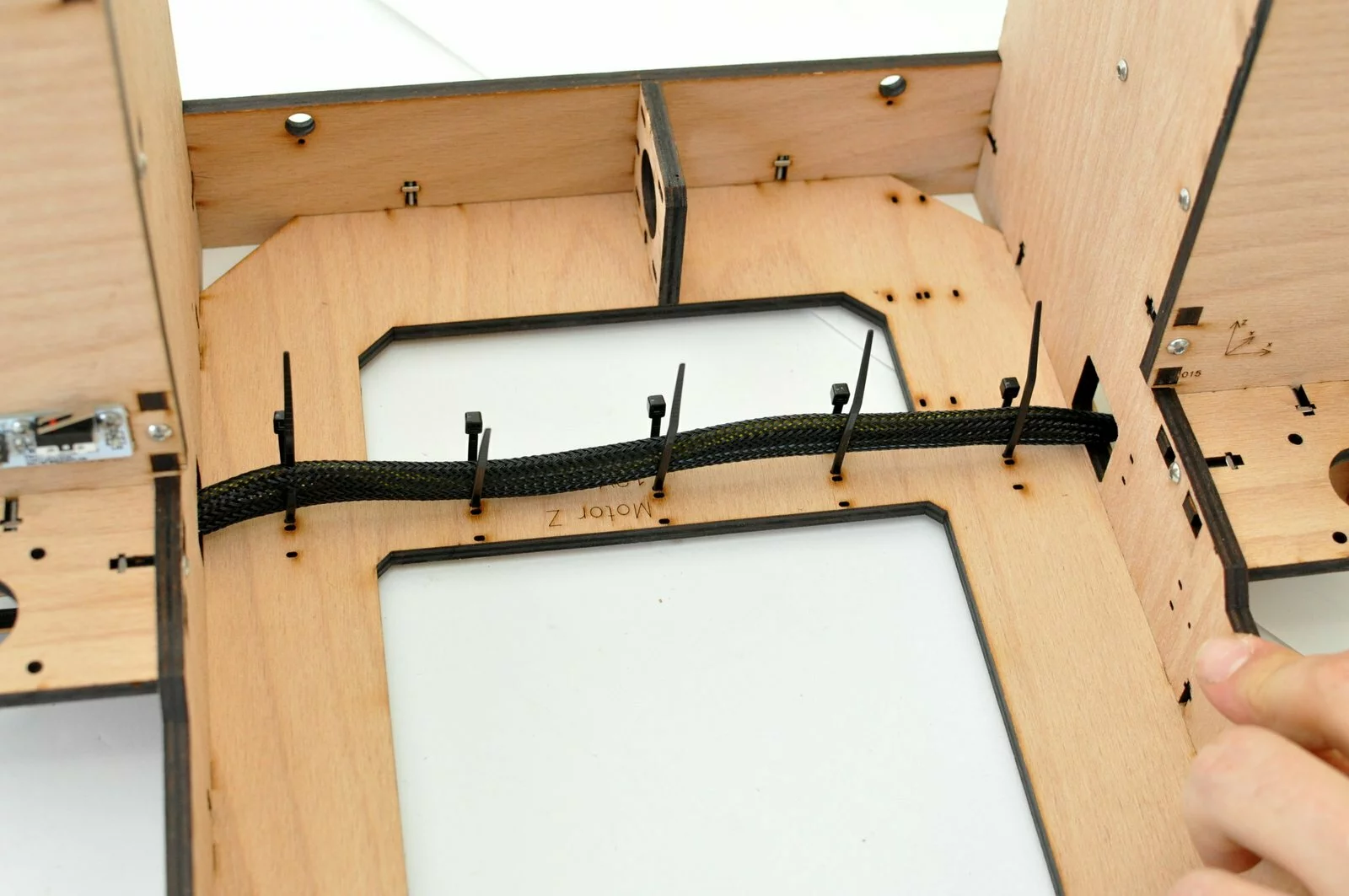
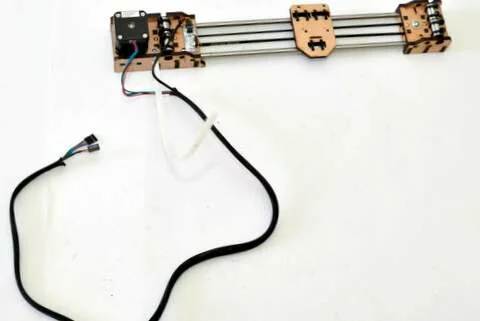
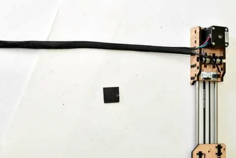
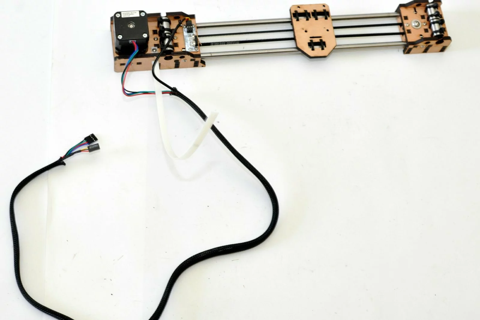
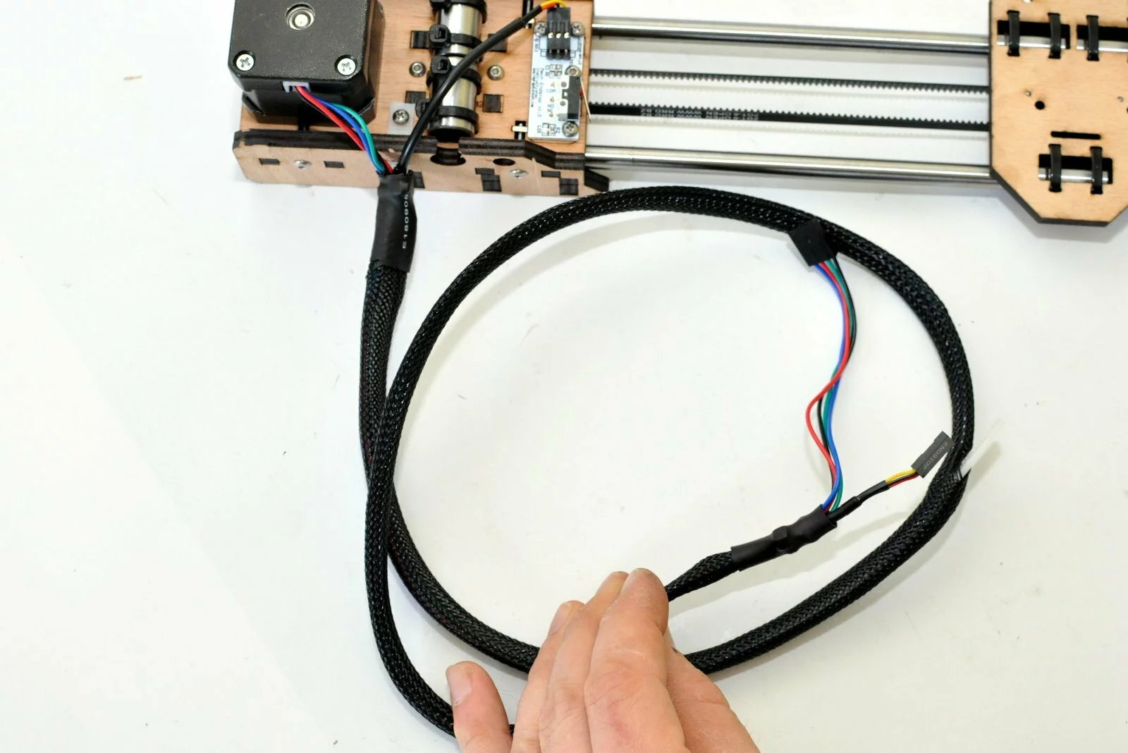
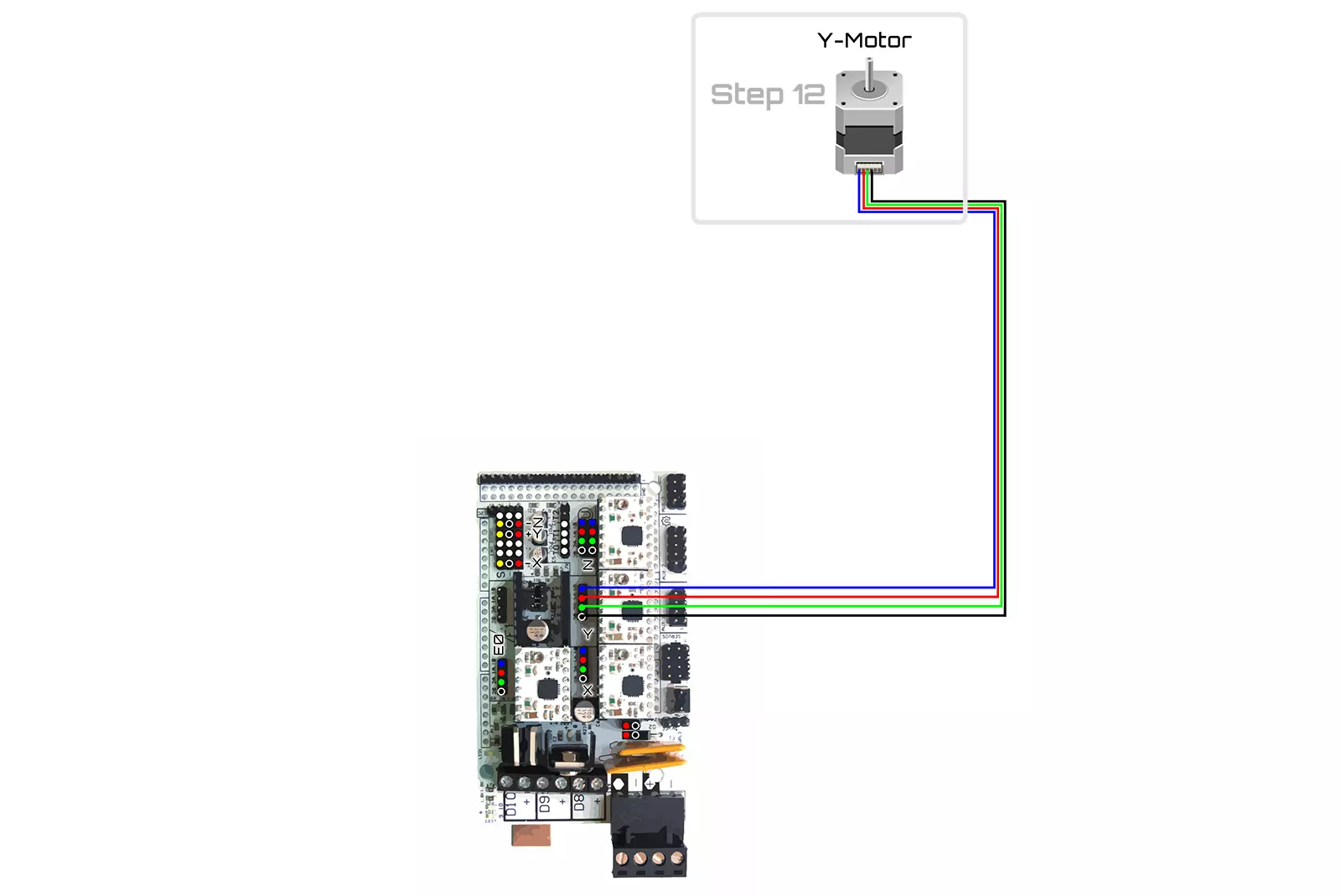
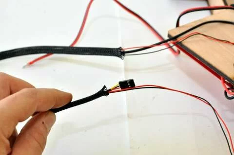
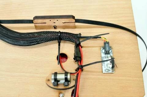
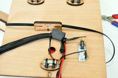
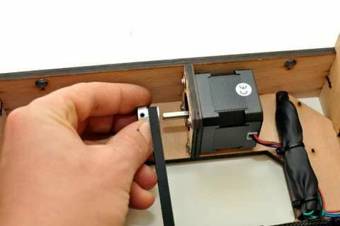
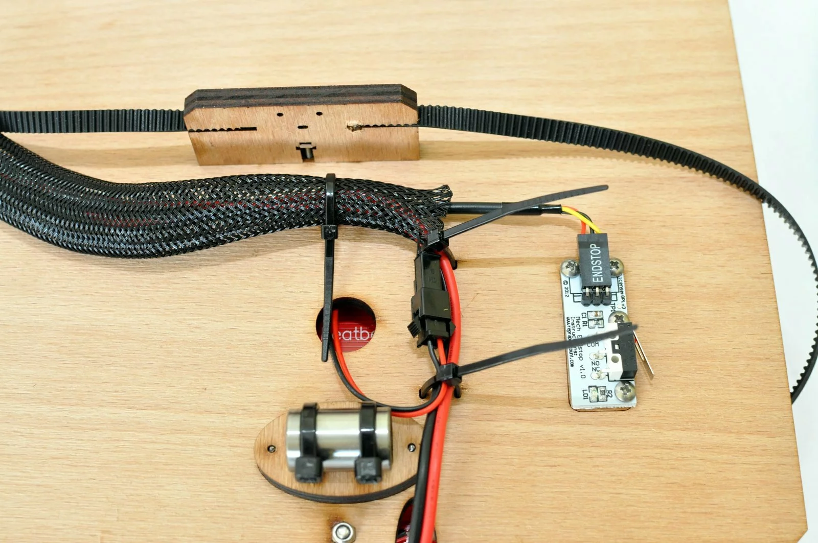
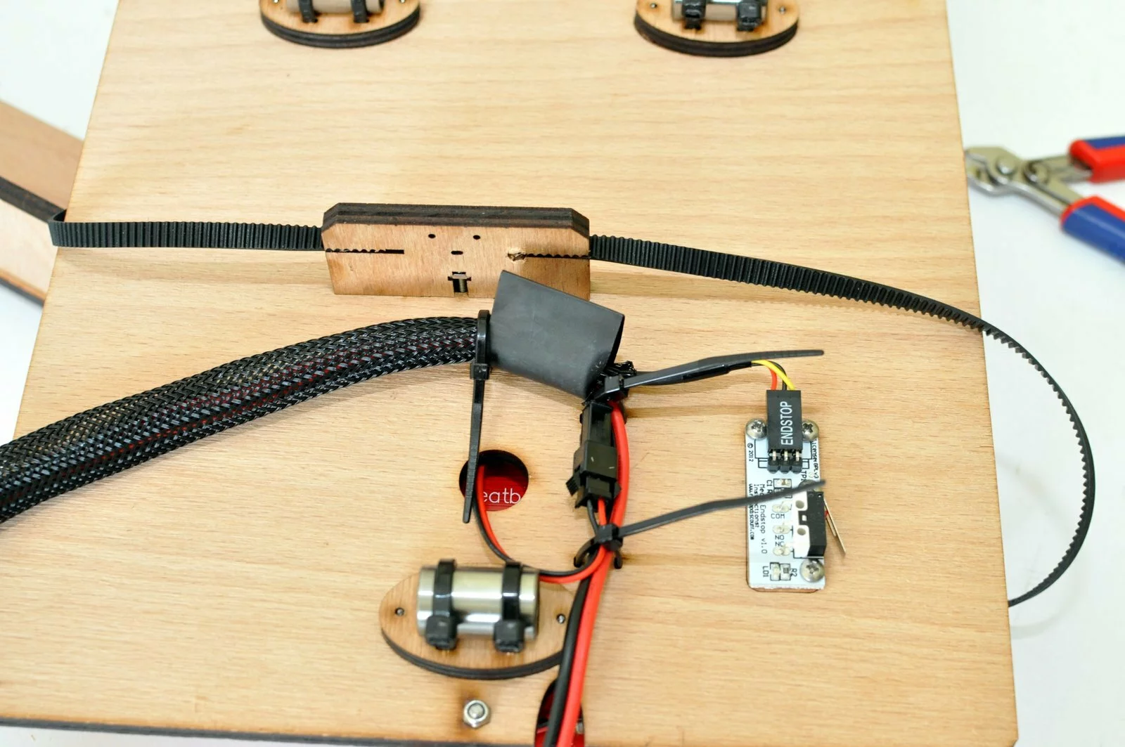
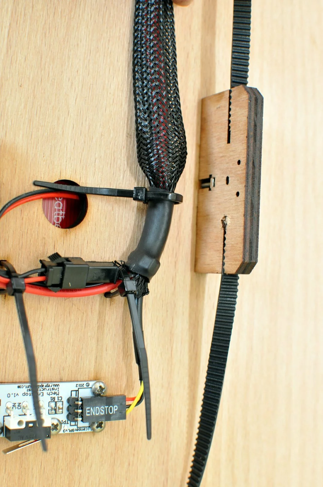
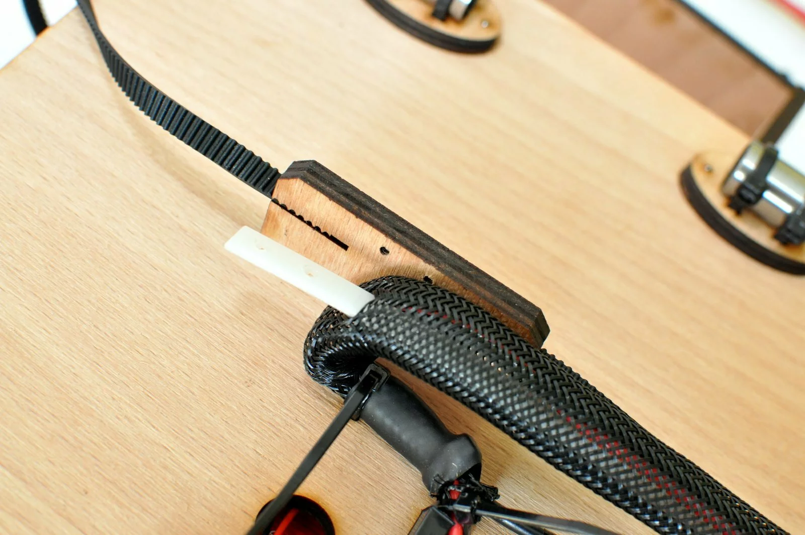
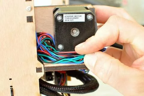
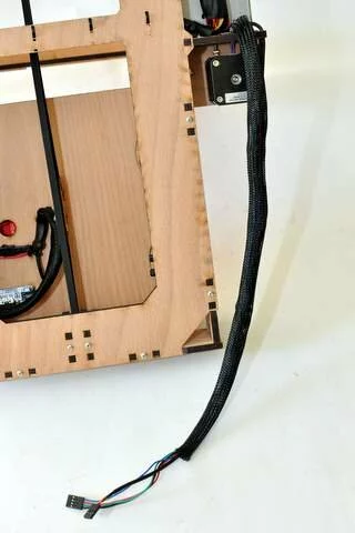
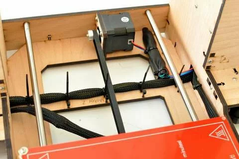
Use the shrink hose to hide the cable of the Y-motor.


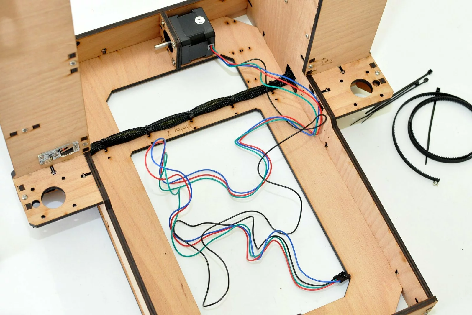


Wiring
Result
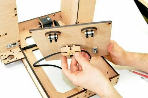
Step 13
Tools
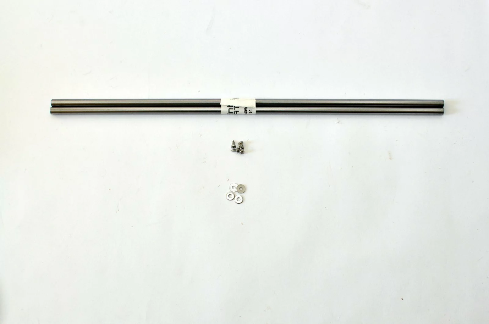
Parts

Video
Steps
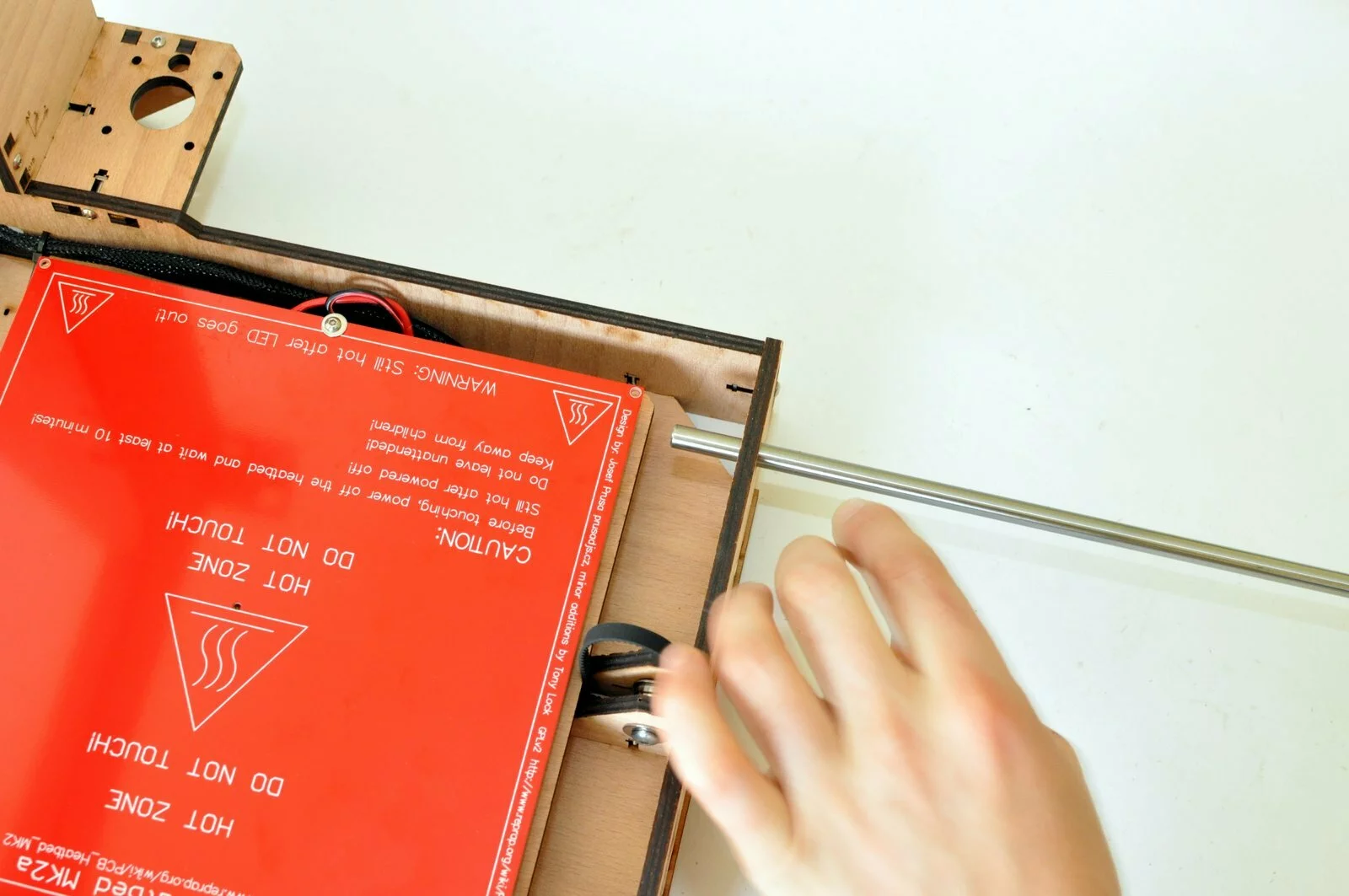
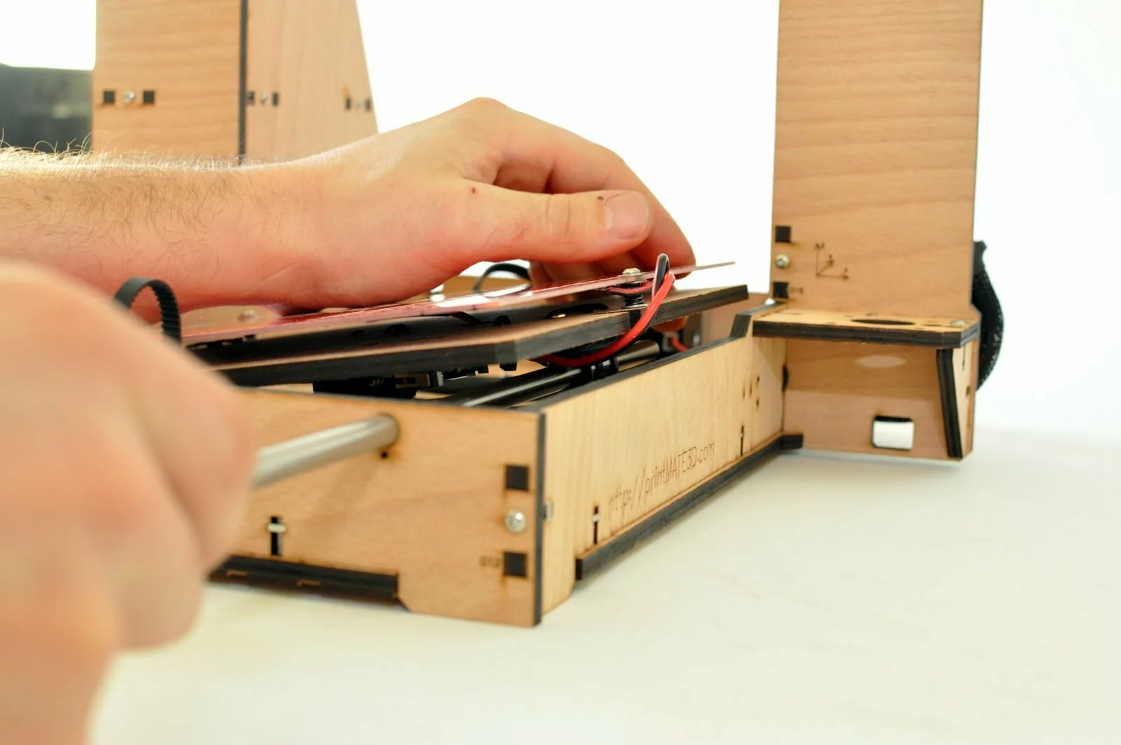
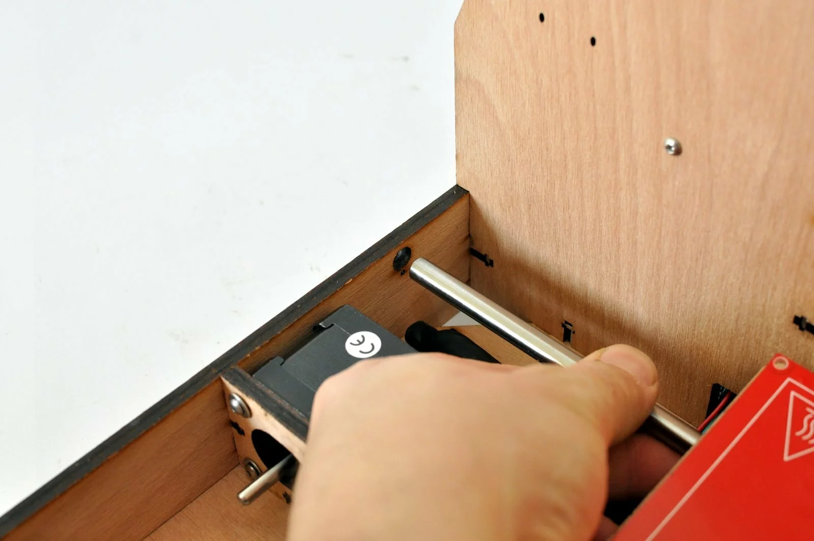
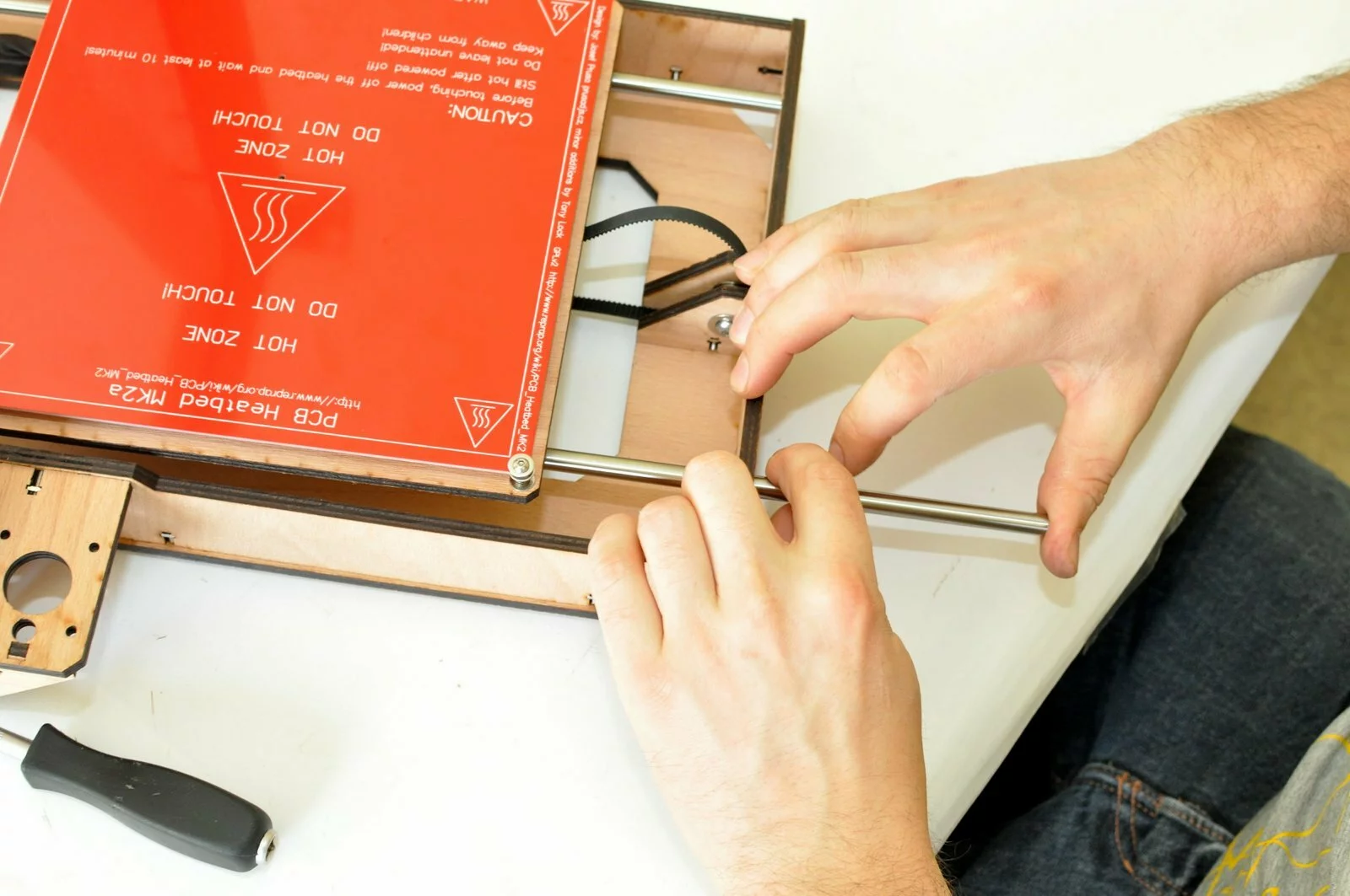
- Step
- Step
- Step
- Step
- Step
- Step
- Step
- Step
- Step
- Step

- Step
- Step

- Step

- Step
- Step
- Step

- Step
- Step
- Step
- Step
- Step
- Step
- Step
- Step


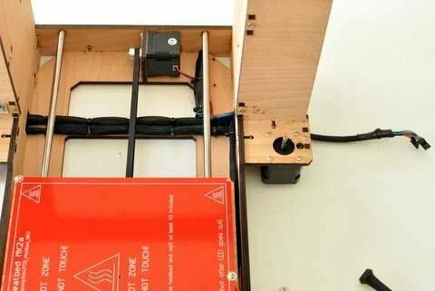
wiring
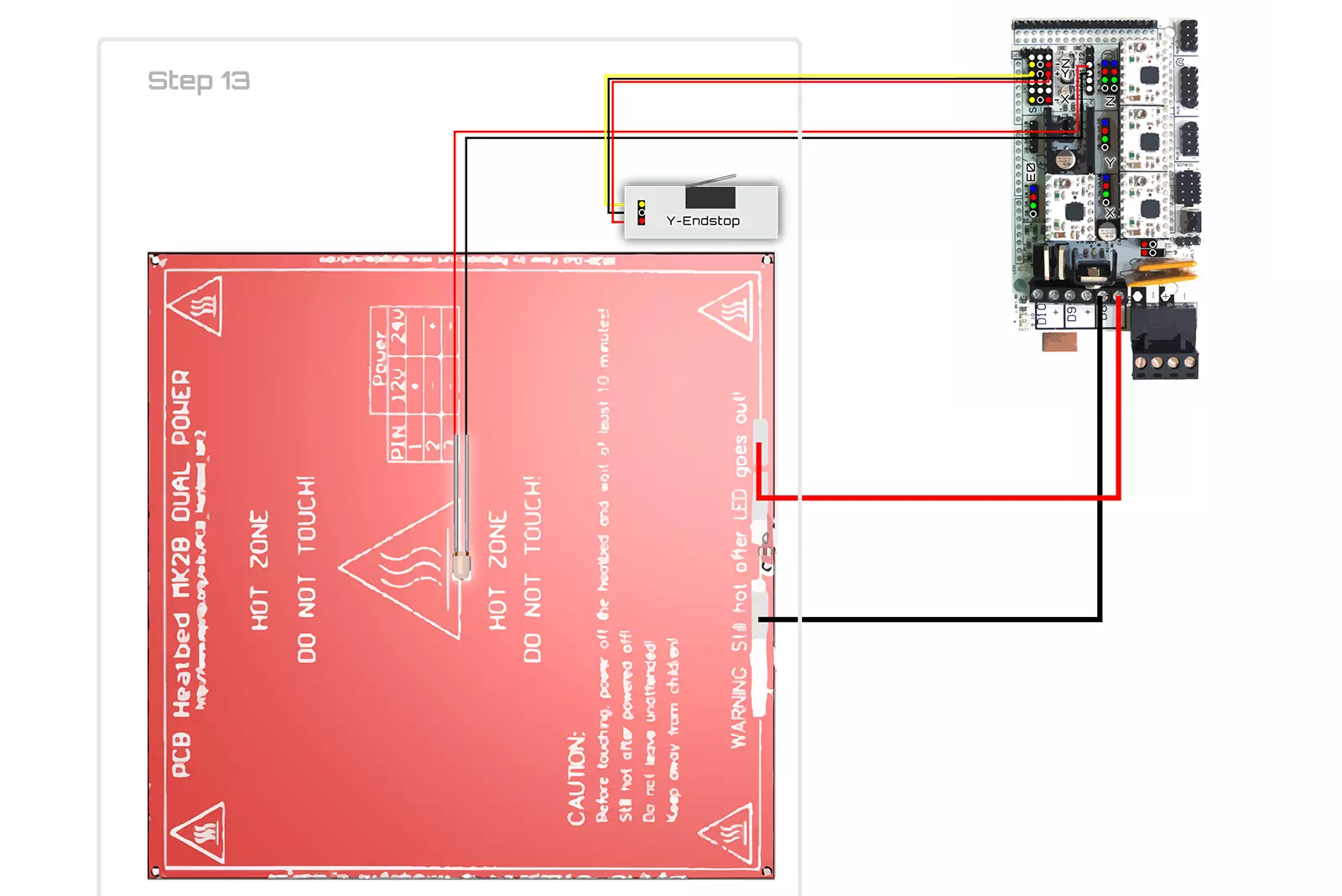
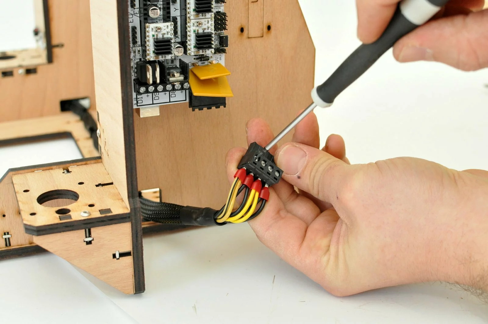
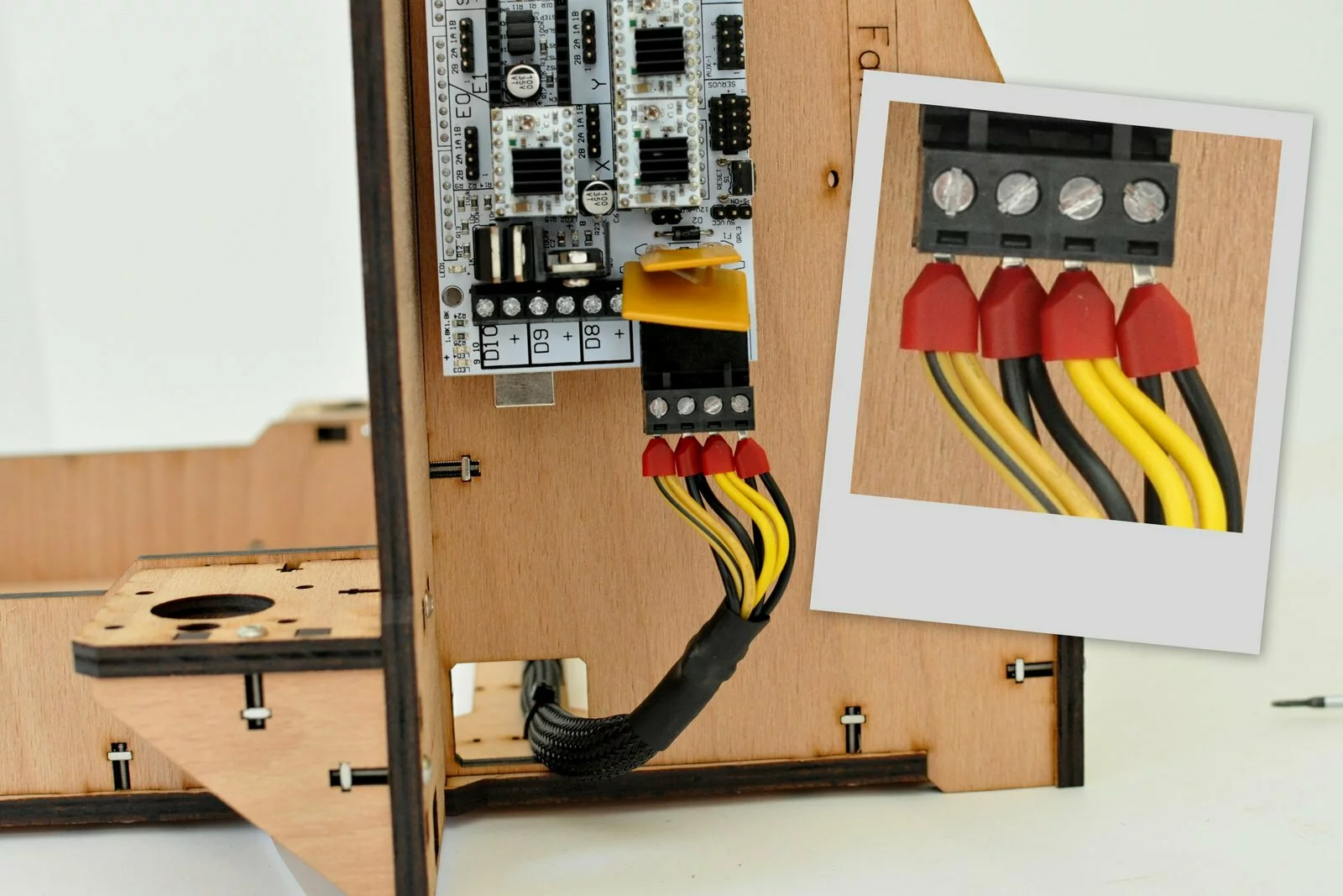
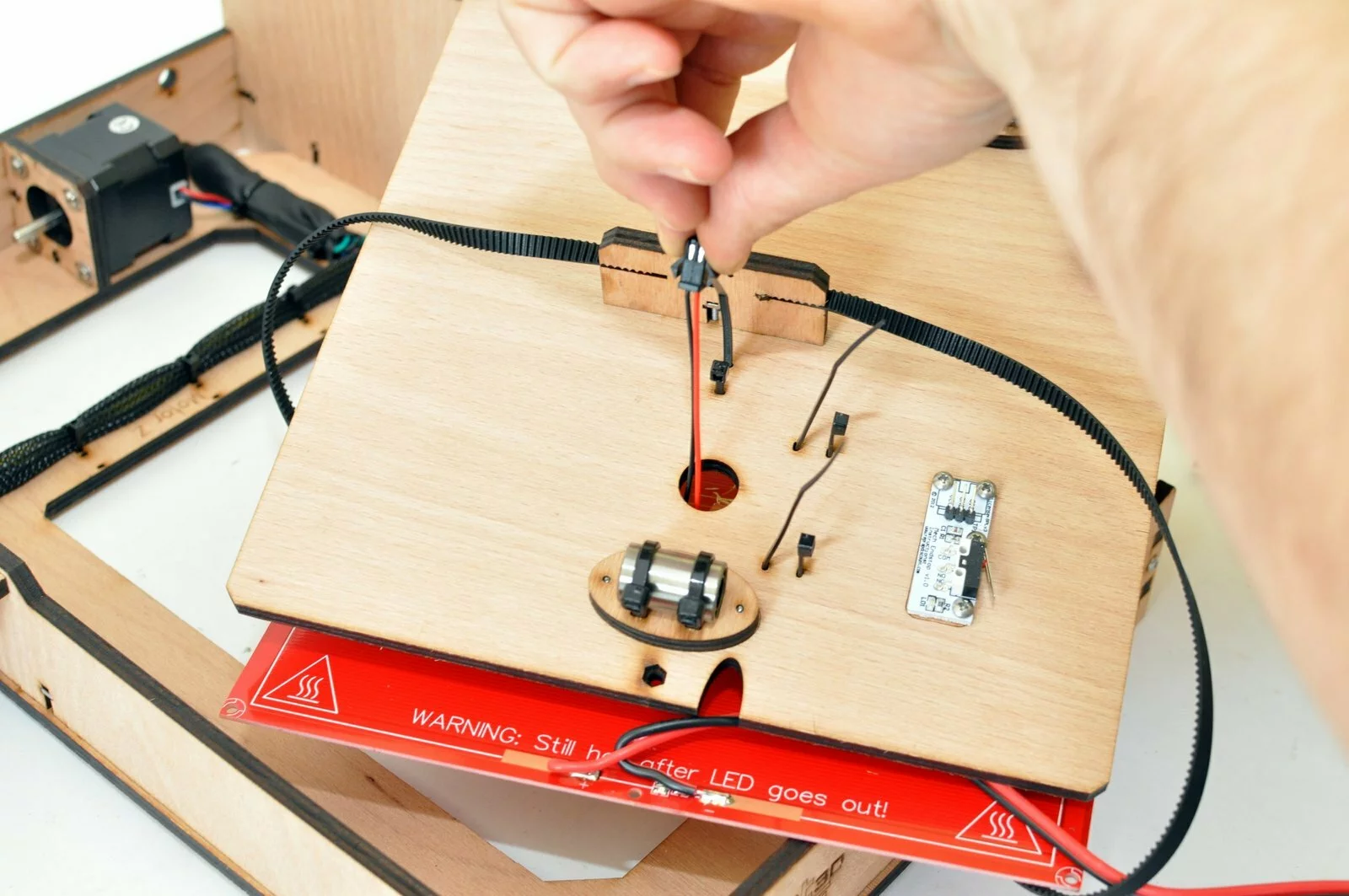
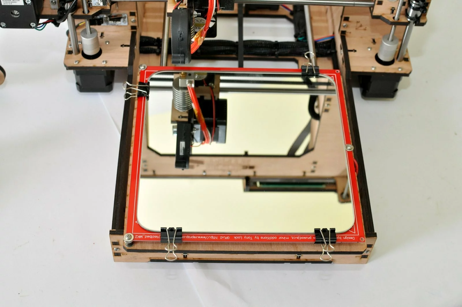
Connect the power supply of the heated bed platform to D8 of the RAMPS (Red is +; Black connects to -)
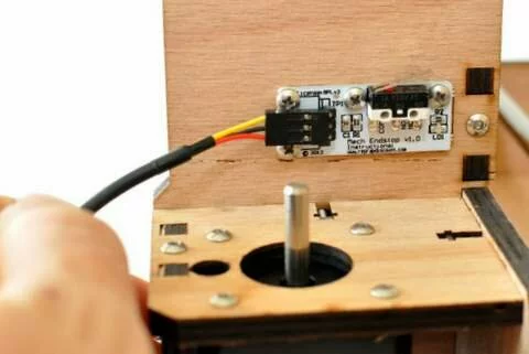
Connect the limit switch cable of the y axis to the Y+ limit switch connector on the RAMPS board.
The thermistorcable of the heatbed is connected to t1 in the thermistor section of the RAMPS board
- Step

Result
Step 14
Tools
Parts
Video

Steps
- Step
- Step

- Step
- Step
- Step
- Step
- Step
- Step

- Step
- Step
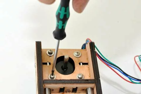
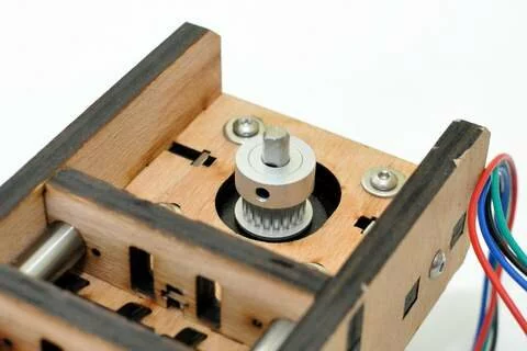
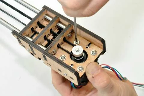
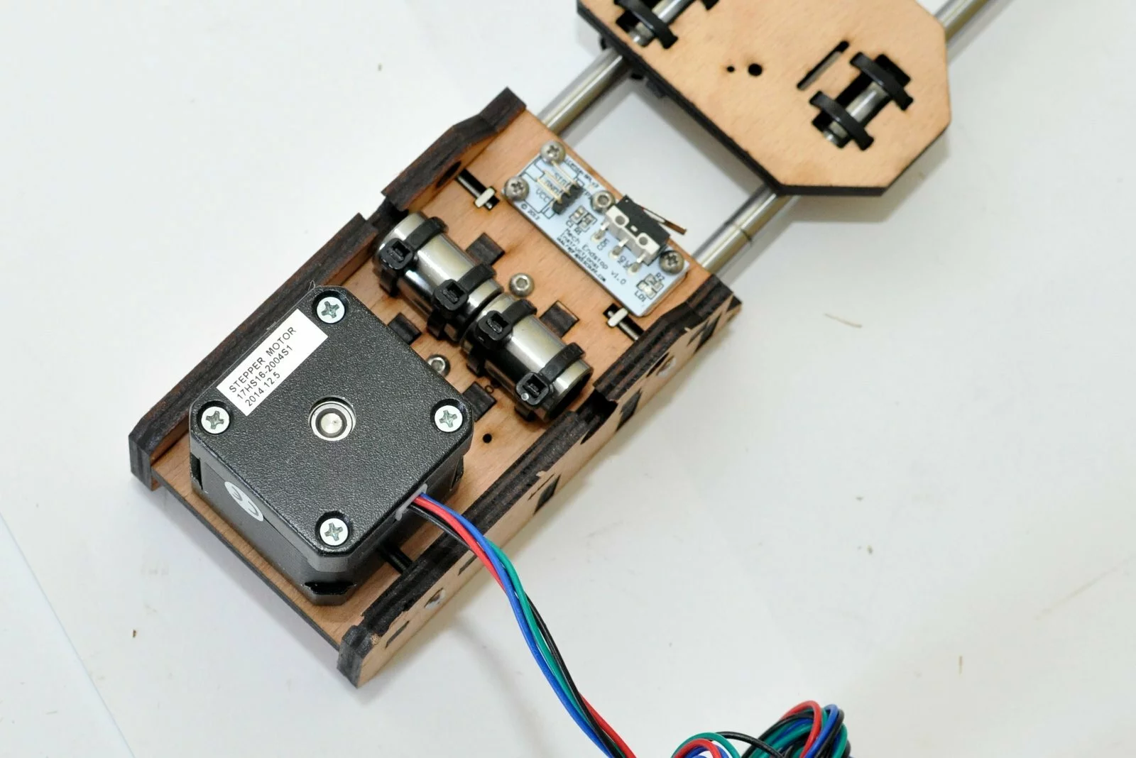
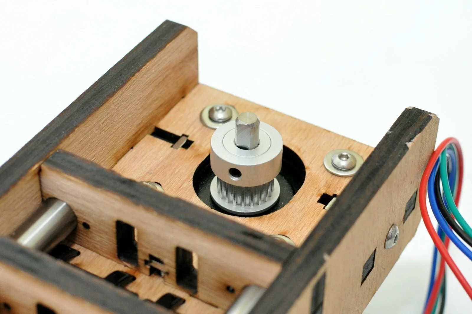
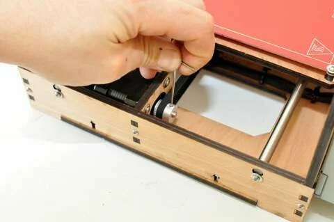
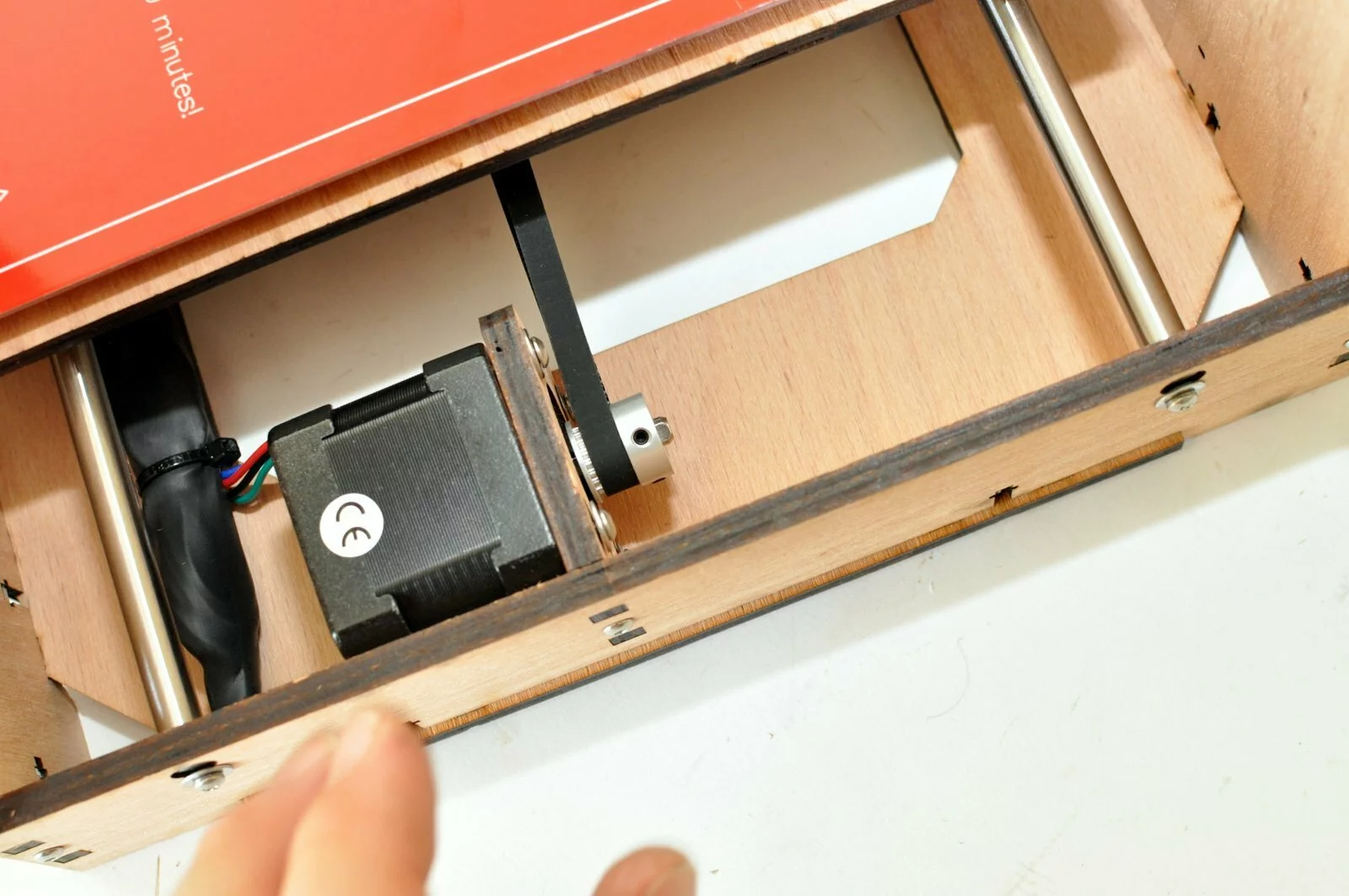
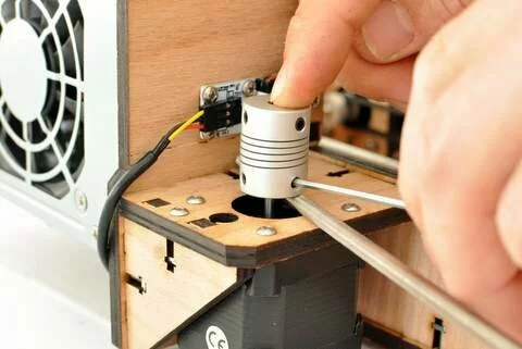
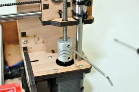
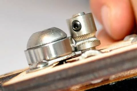
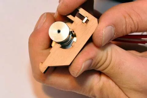
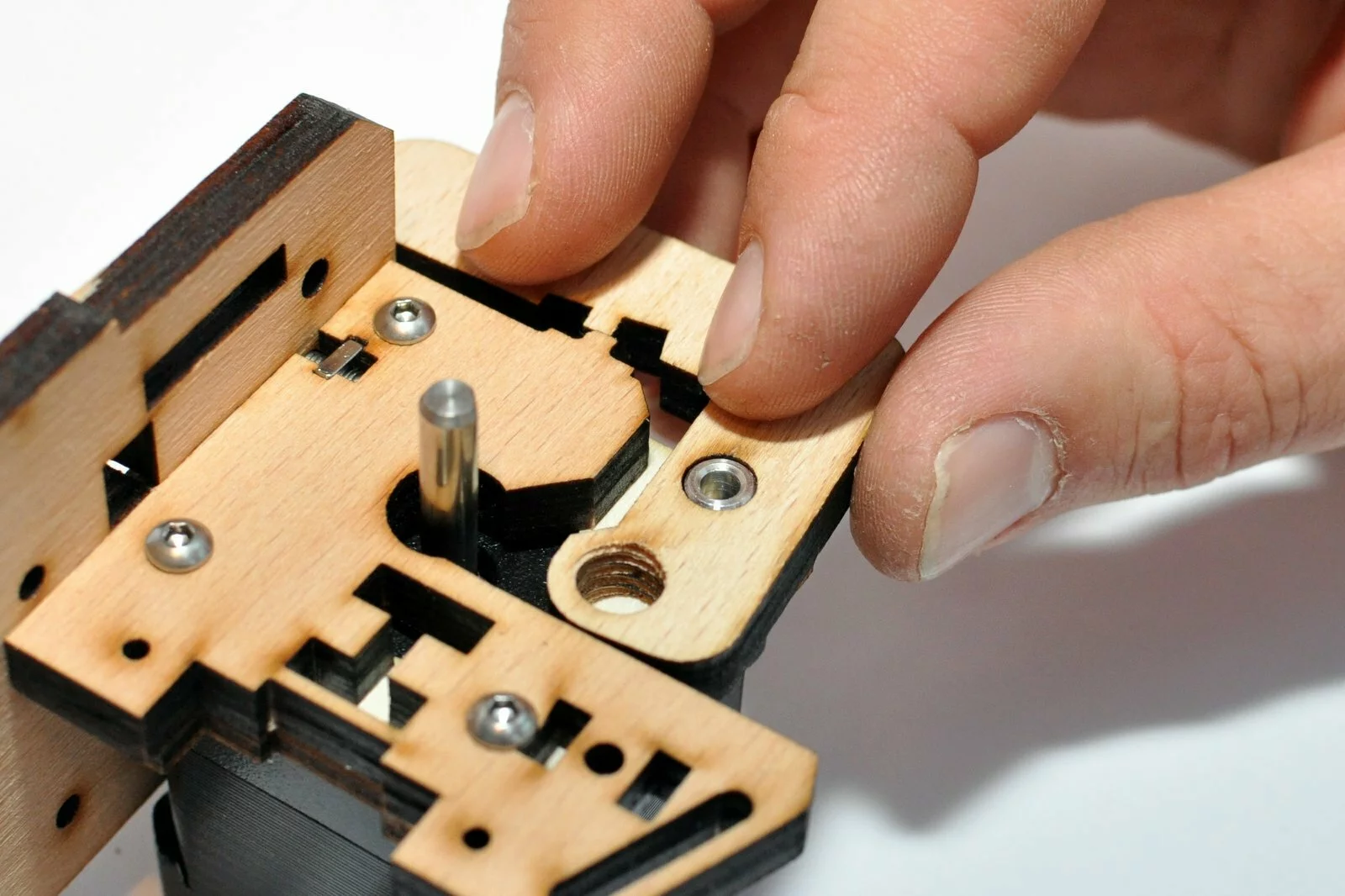
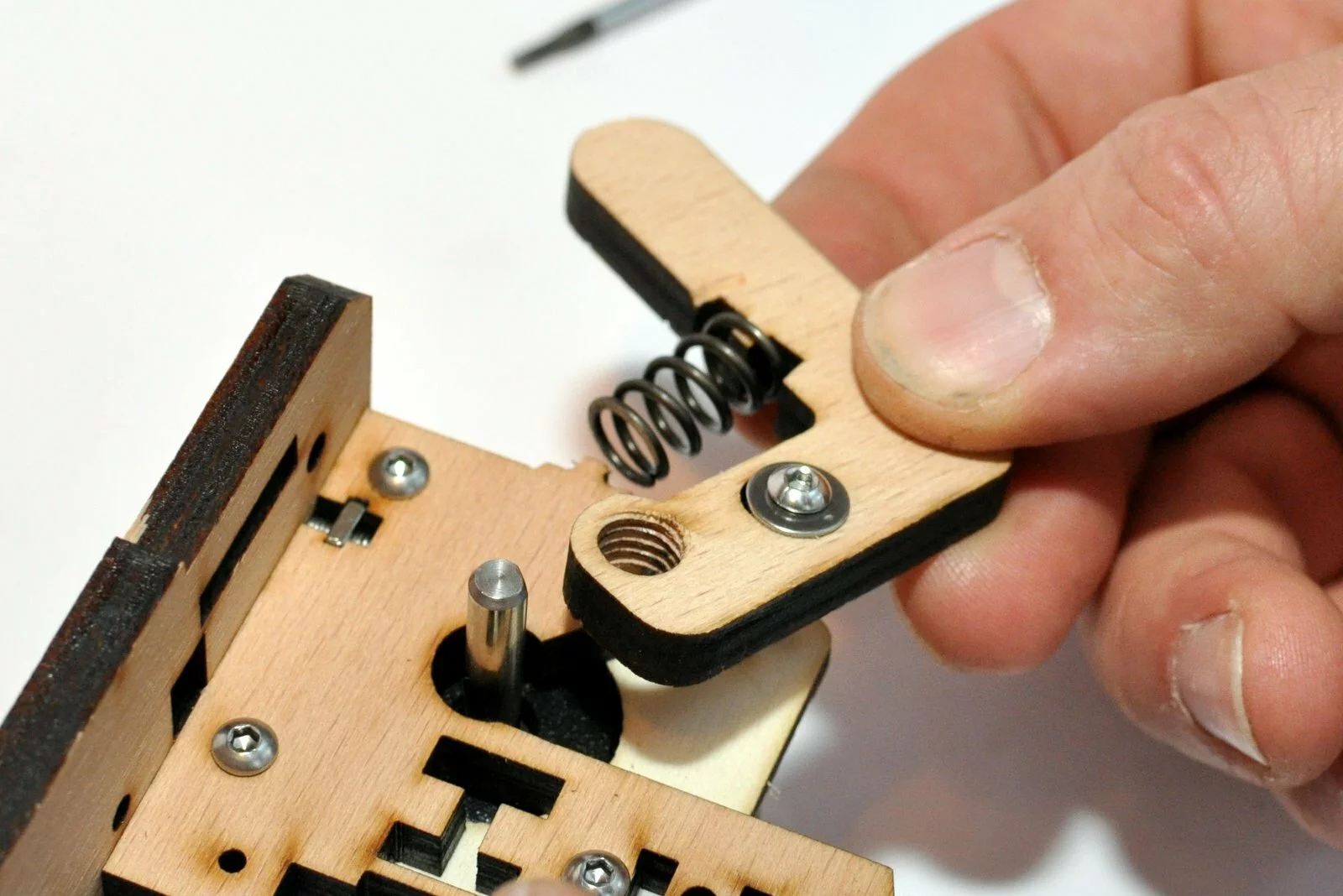
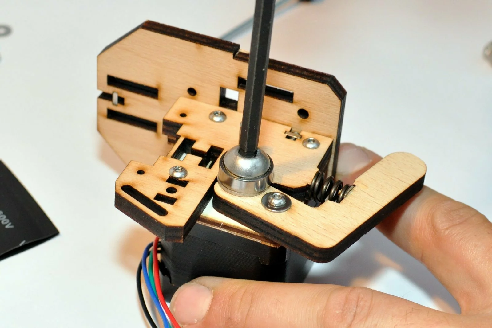
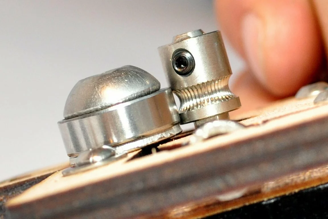
Make sure you are able to tension the belt by the adjustment travel. To prove this you don’t need to fix the screws of the pulley. Just slip it onto the motor shaft and try to tension the belt. Fix the screw of the pulley after you have tensioned the belt.


Result
Step 15
Tools
Parts
Video

Steps
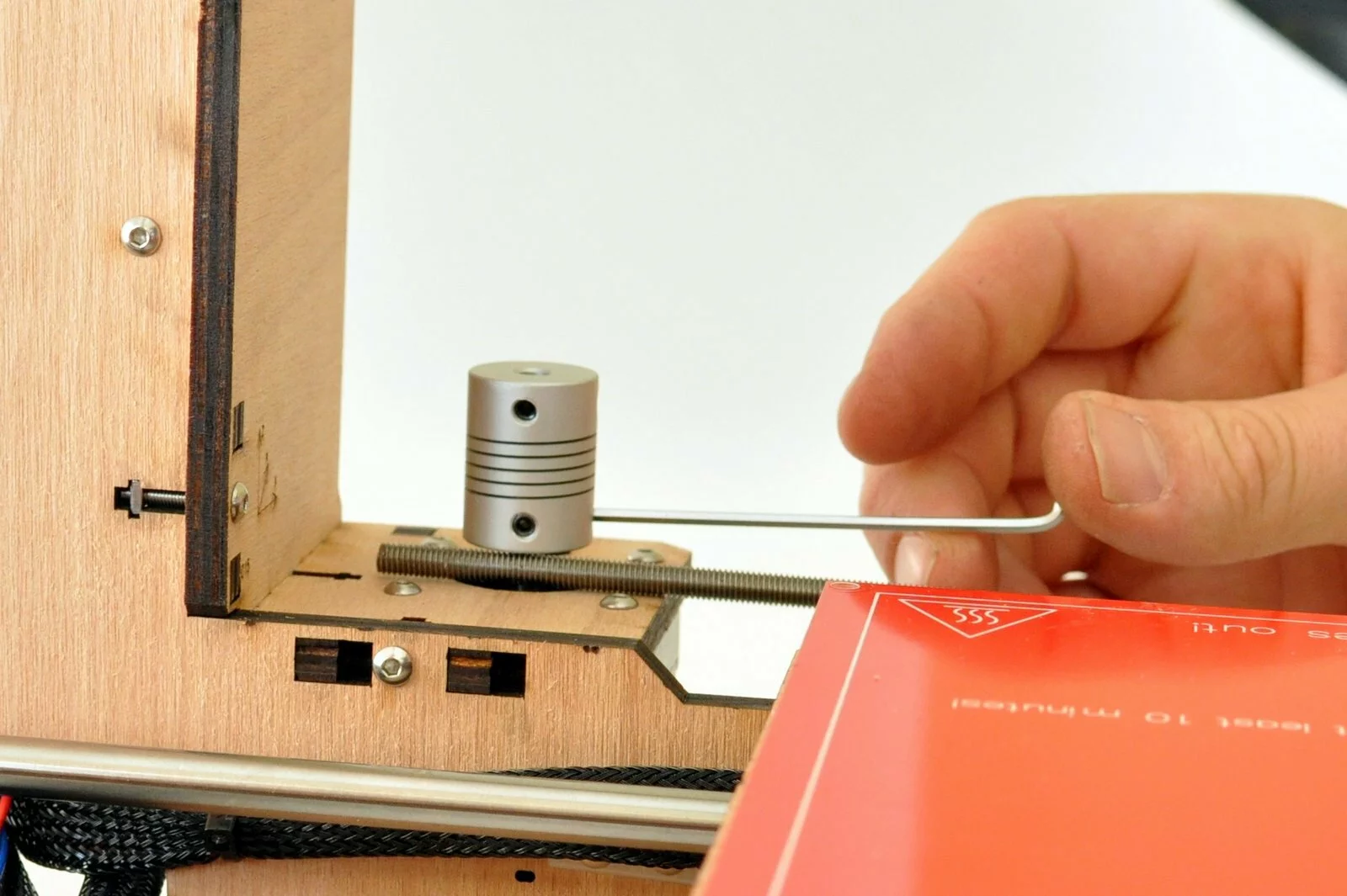
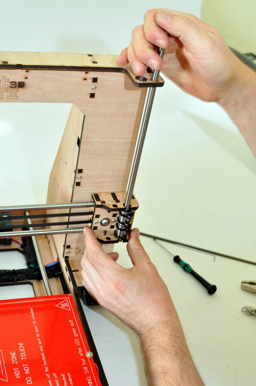
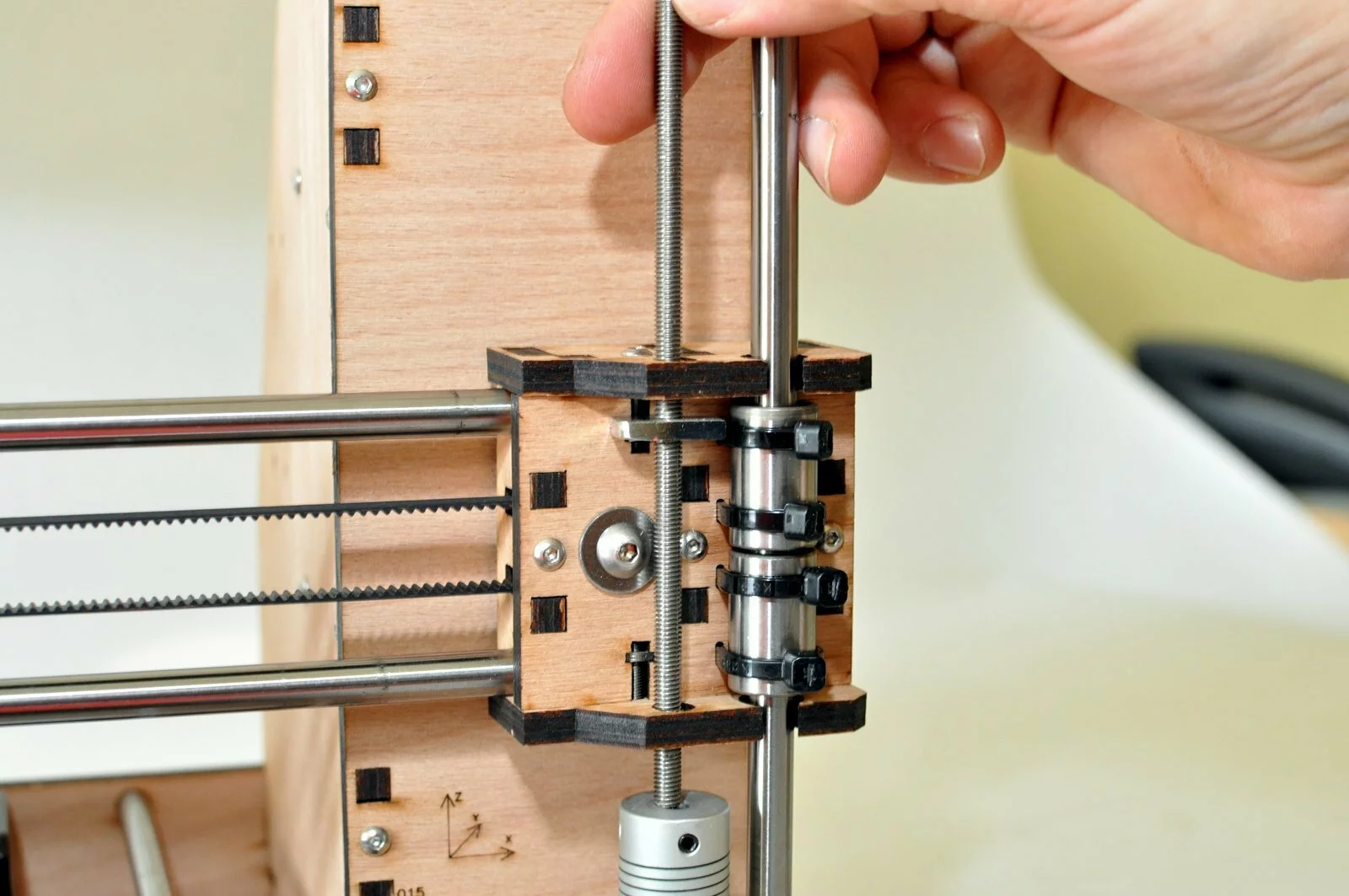
- Step
- Step

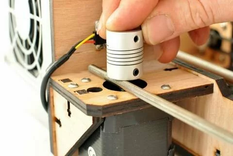
Connect the Z-motors to the Z-driver on the RAMPS board - Step
- Step
- Step
- Step

- Step
- Step
- Step
- Step


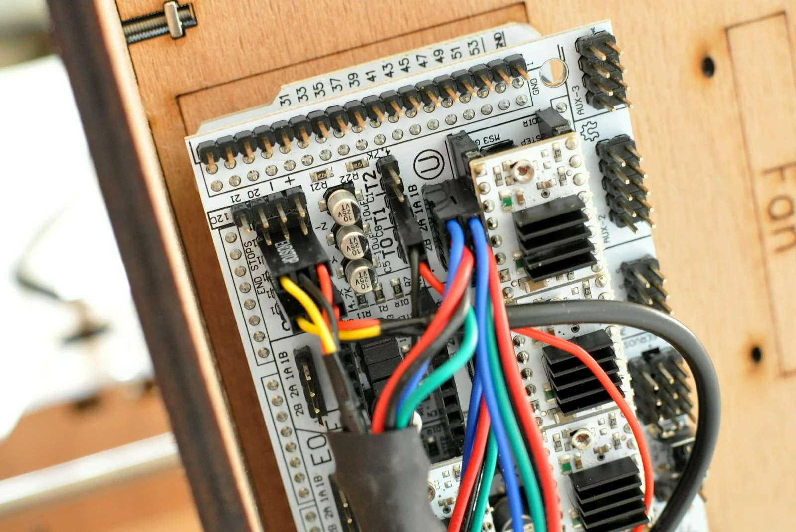
wiring
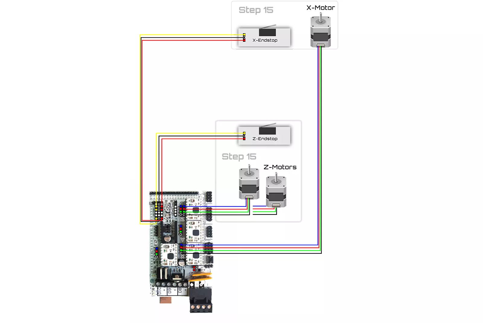
connect the left motor of the Z-axis to the Z-motor driver. The Endstop for the Z-axis is connected to Z- in the limit switch section.
- Step

- Step
- Step
- Step
- Step

- Step
- Step
- Step

- Step

- Step
- Step
- Step
- Step
- Step

- Step
- Step

- Step
- Step
- Step


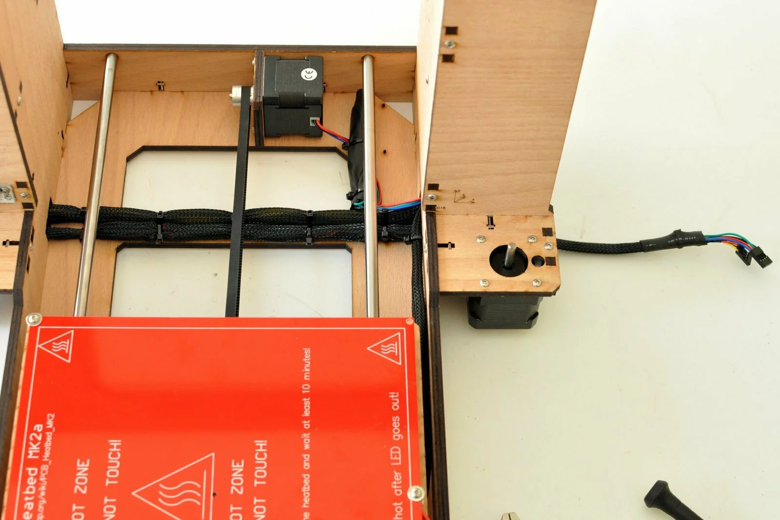
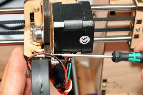
wiring
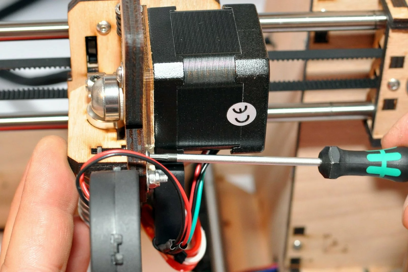
connect the plug for the x-axis stepper motor and the cable for the limit switch (X- in the limit switch section)
Result
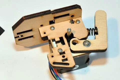
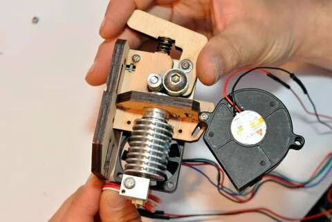
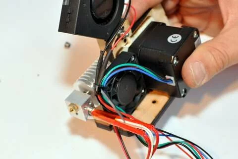
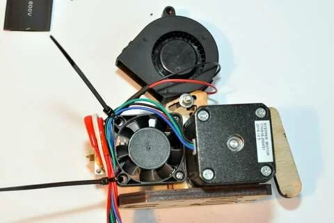
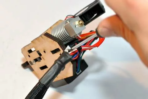
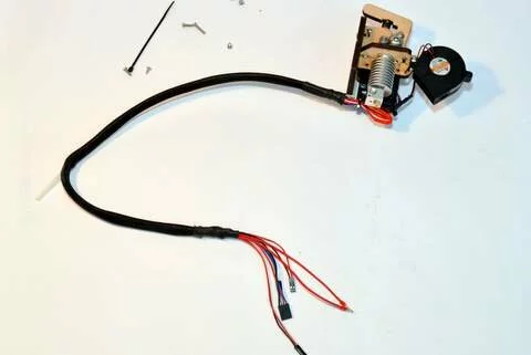
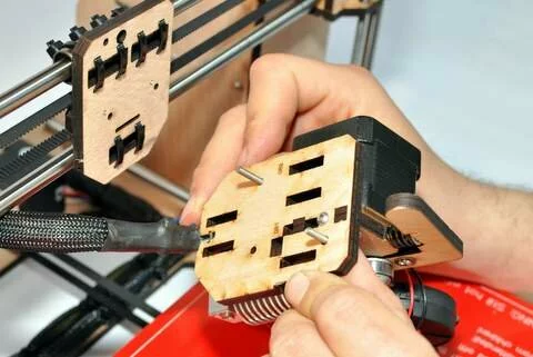
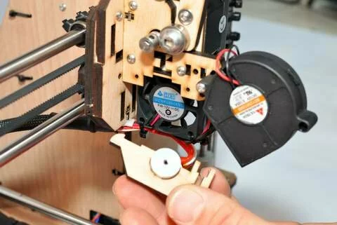
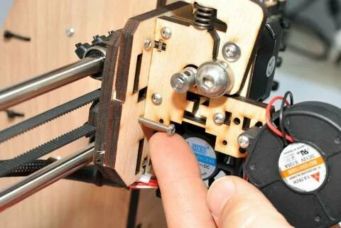
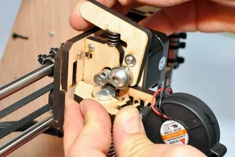
Step 16
Tools
Parts

Video

Steps
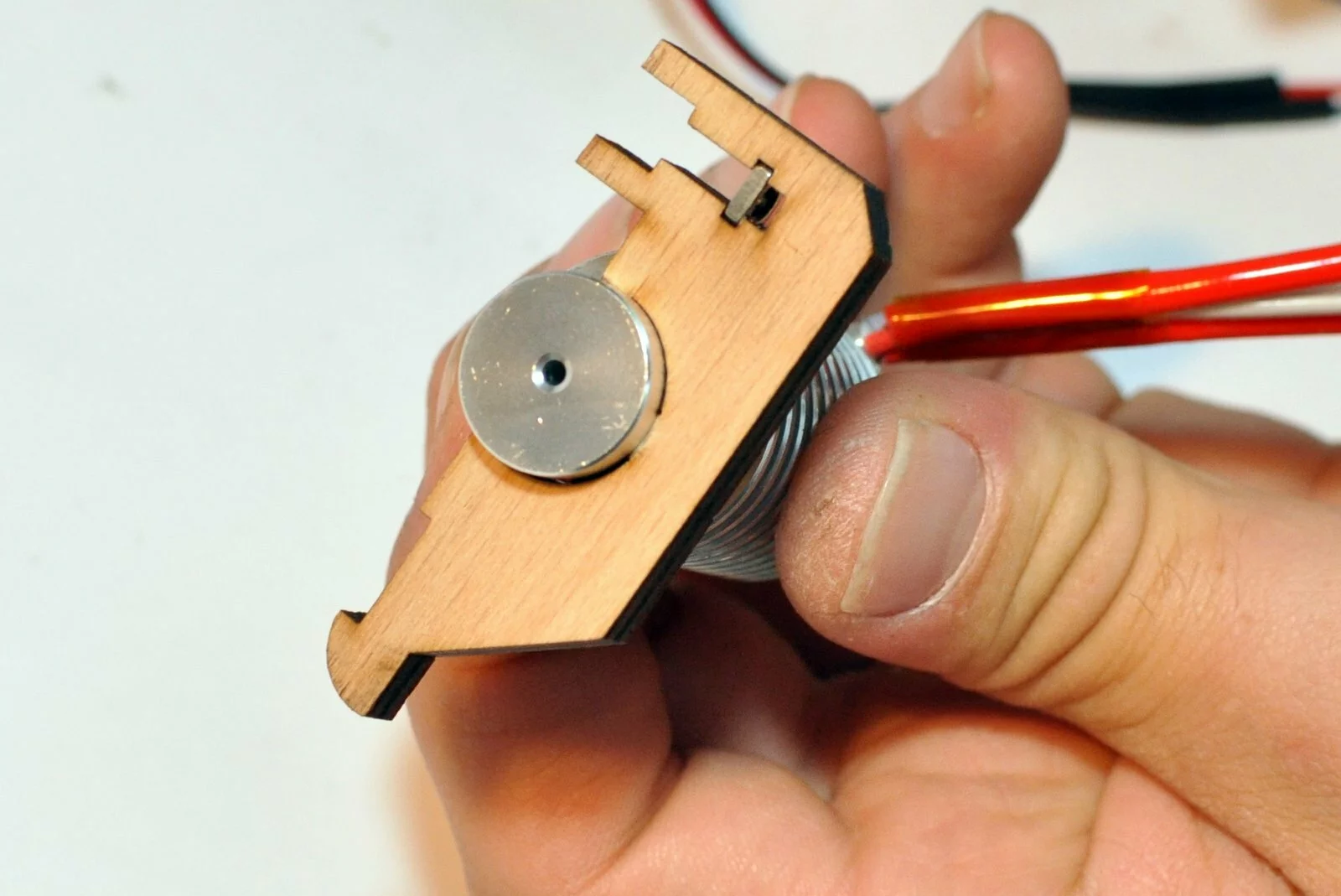
- Step
- Step
- Step

- Step
- Step
- Step
- Step
- Step

- Step
- Step
- Step
- Step
- Step
- Step
- Step
- Step
- Step
- Step

- Step
- Step
- Step

- Step
- Step
- Step
- Step
- Step
- Step
- Step
- Step
- Step
- Step
- Step


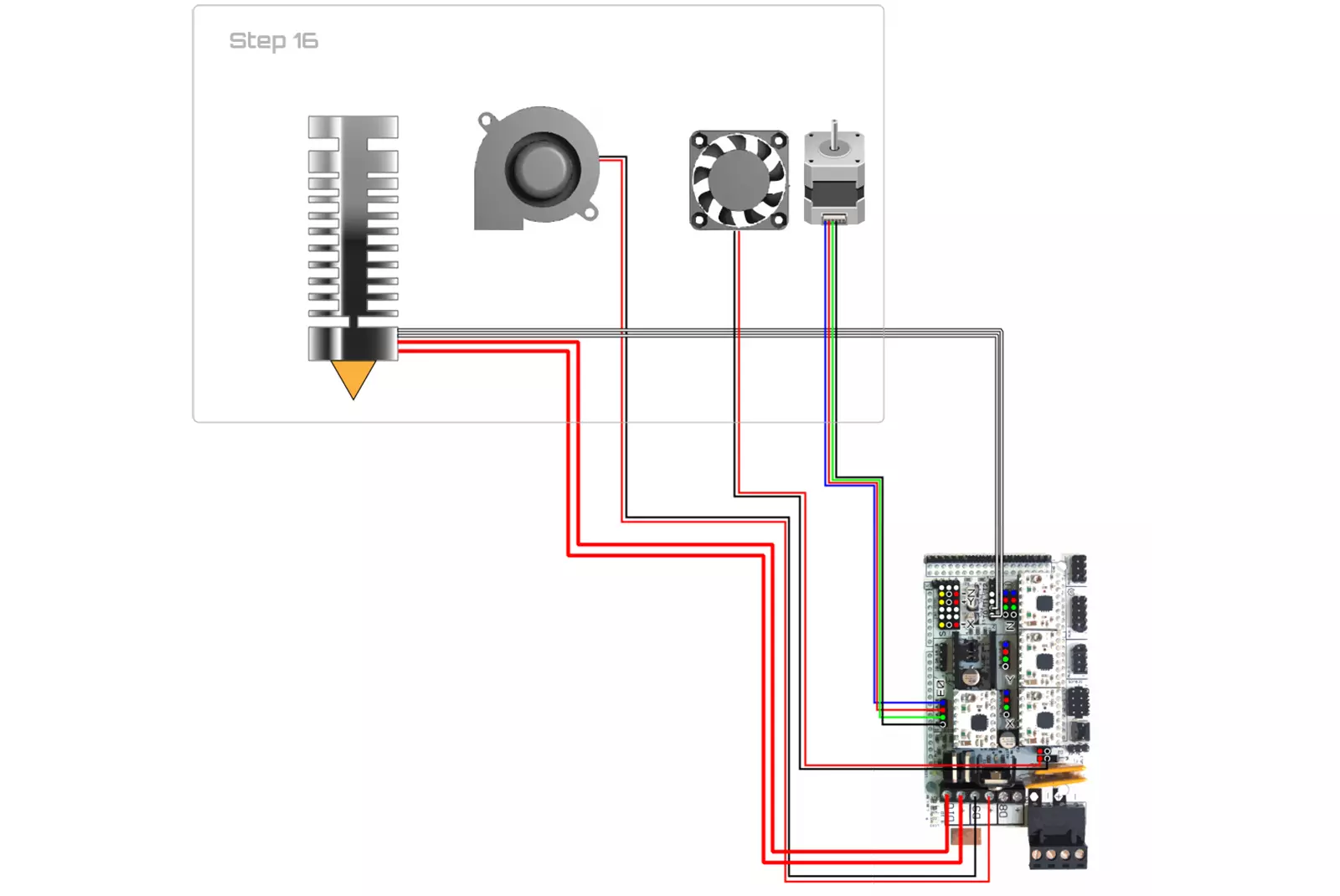
wiring
Result
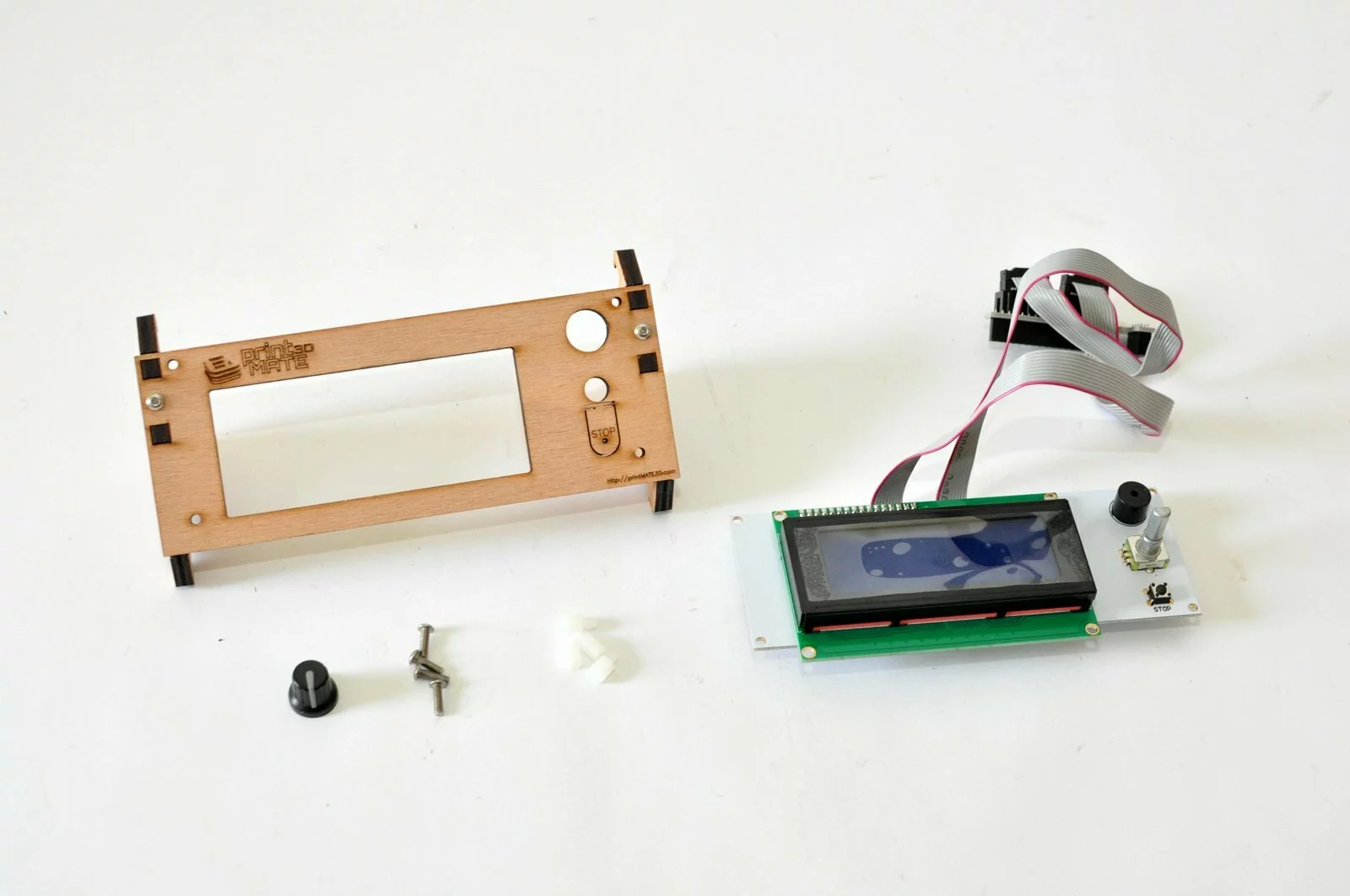
Step 17
Tools
Parts
Video

Steps
- Step
- Step
- Step
- Step

- Step
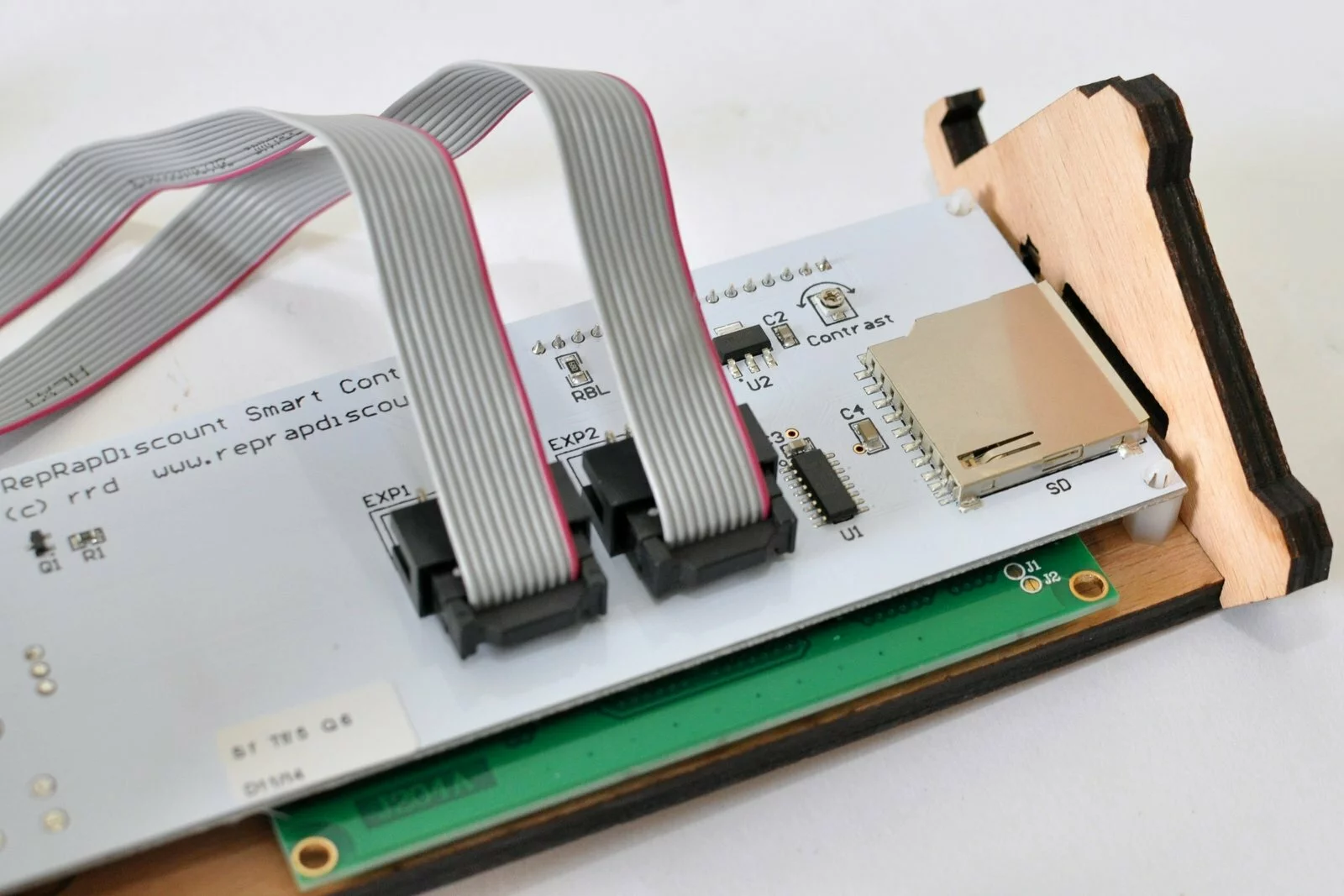
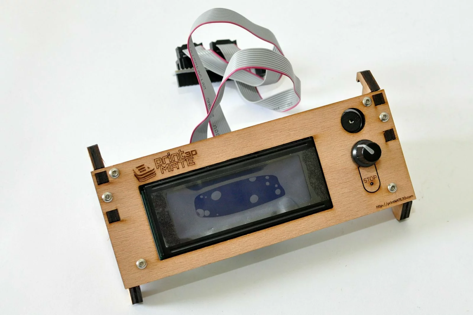
Result
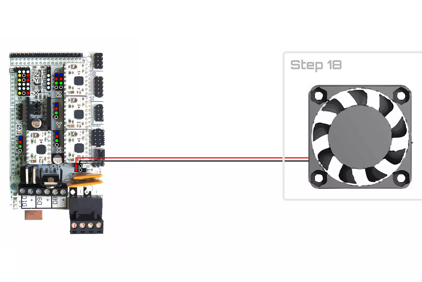
Step 18
Tools
Parts
Video

Steps
- Step

- Step

- Step
- Step
- Step

- Step
- Step
- Step


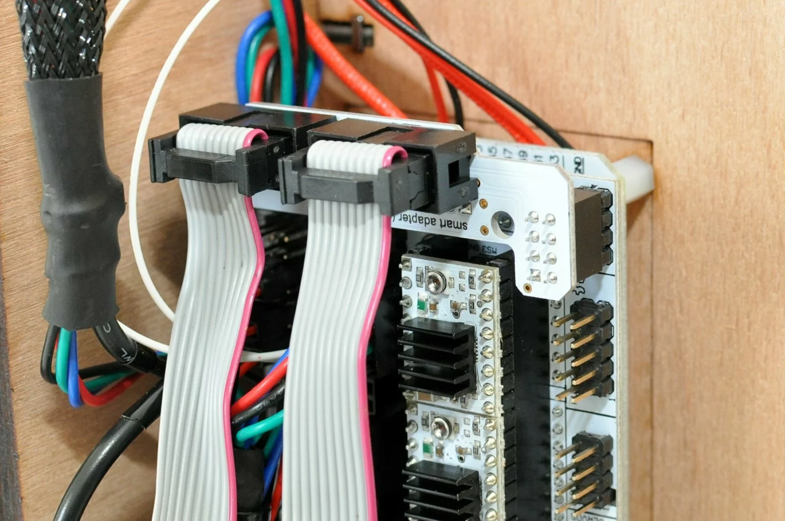
wiring
Result
wiring overview